Front Enclosure Assembly
When assembled, the front enclosure has an acryllic door, top window, and opaque sides. Sealable cutouts are provided for front handles (to easily lift it out of the way when necessary) and the spool holder on the side.
Attach the Front Door
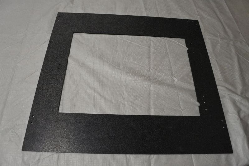
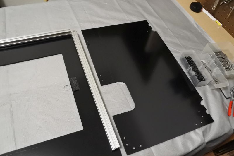
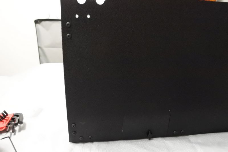
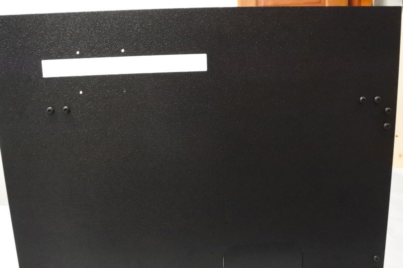
Find the front plate. All plates are named for where they will be when the enclosure is assembled and installed and viewed from the front. The front plate typically presents its hair cell texture to the outside of the enclosure. The door opens on the left with hinges on the right. However, the plate could be flipped horizontally if you need the door to open on the right instead.
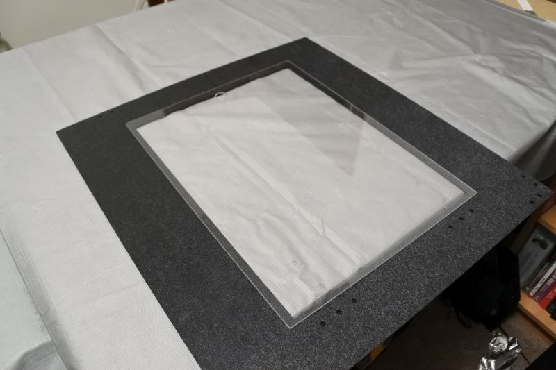
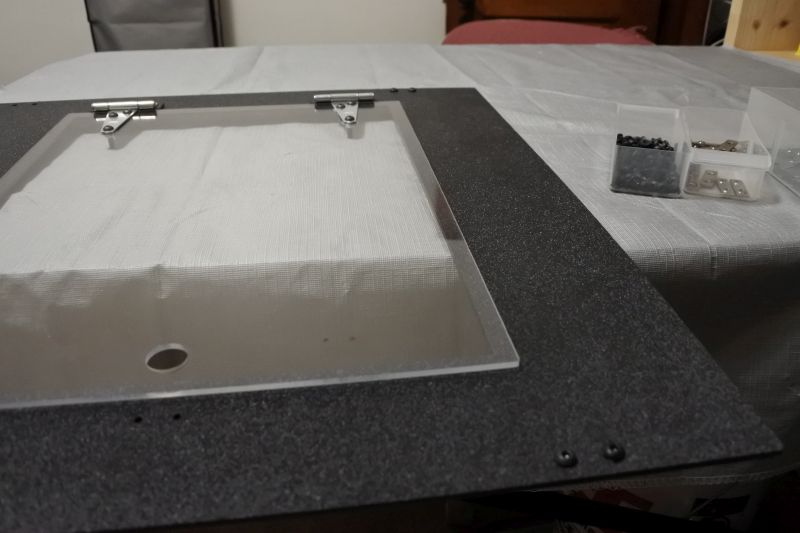
The Front Door is the largest acrylic plate. Make sure to remove the opaque protective film at this stage. Then place it on top of the Front Plate near the hinge mounting holes. Because of the hole pattern of the hinges, it is not symmetrical. If you find that the hinge holes don't line up later, simply flip the Front Door around.
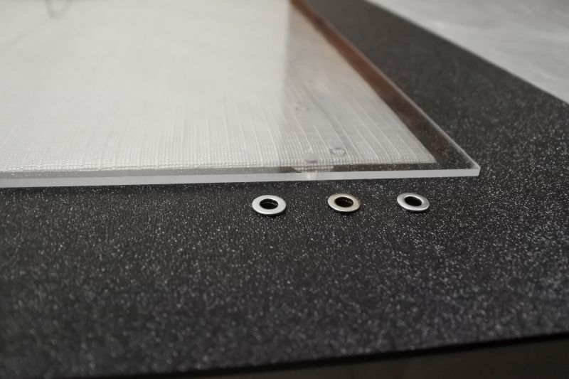
Place (3) M5 Washers on top of hinge mounting holes on one side of the Front Plate. These M5 Washers act as spacers to let the Front Door open and close properly.
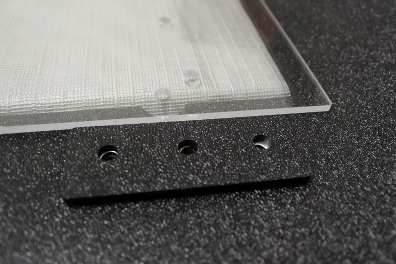
Place a (1) Hinge Shim on top of the M5 Washers. The holes on the Hinge Shim are closer to one side than the other. You want the closer side to be on the same side as the Front Door.
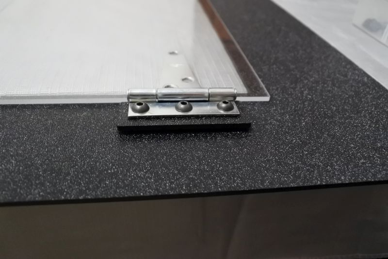
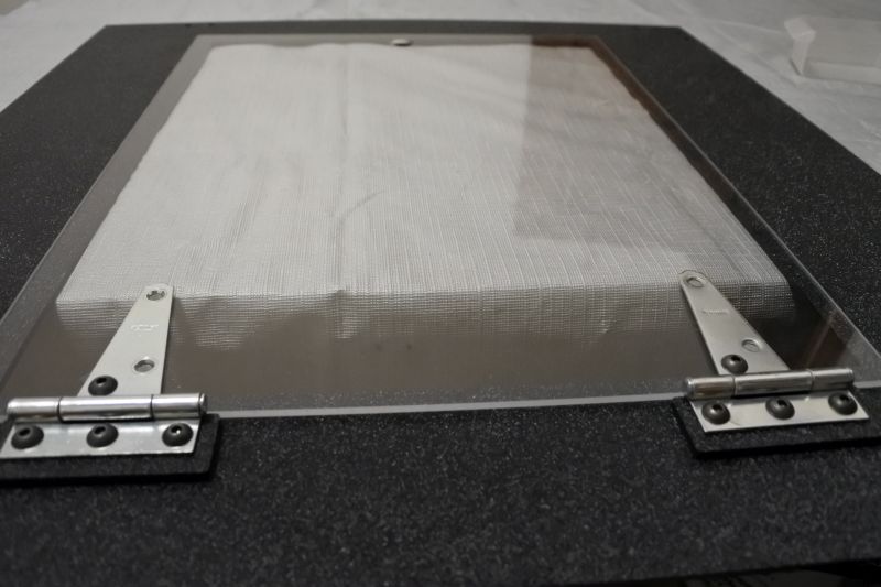
Place (1) Hinge on top of the Hinge Shim and push (3) M5 x 16mm Screws through the holes. Be careful that each screw goes through the Hinge, then the Hinge Shim, then an M5 Washer, and finally the Front Plate.
Thread (3) M5 Nuts onto the M5 x 16mm Screws. Then repeat on the other side. Only finger tighten the M5 Nuts for now.
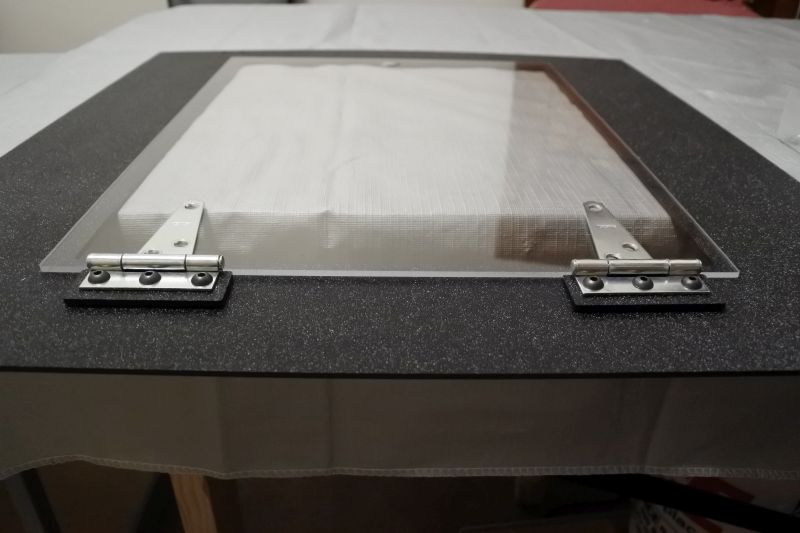
Both hinges should now be secure on the Front Plate. Before the next stage, flip the Front Door if needed to align the hinge holes.
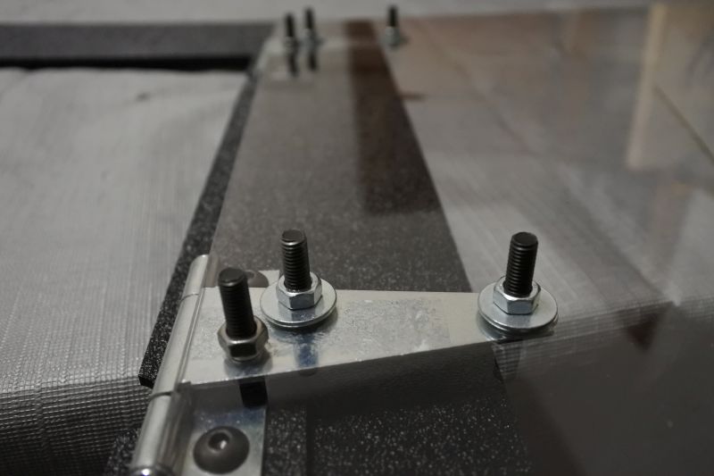
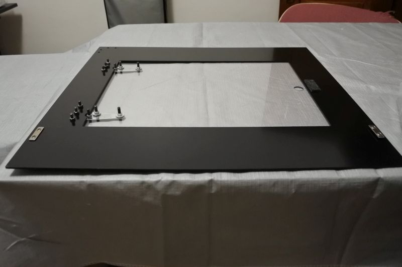
Push an M5 x 16mm Screw through the first hole on each hinge.
The first hole does not require a fender washer, so simply secure the screws with an M5 Nut each finger tight.
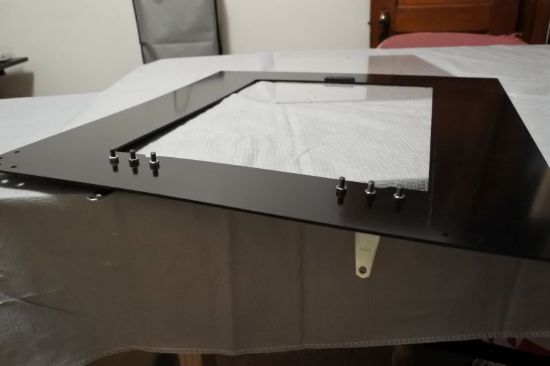
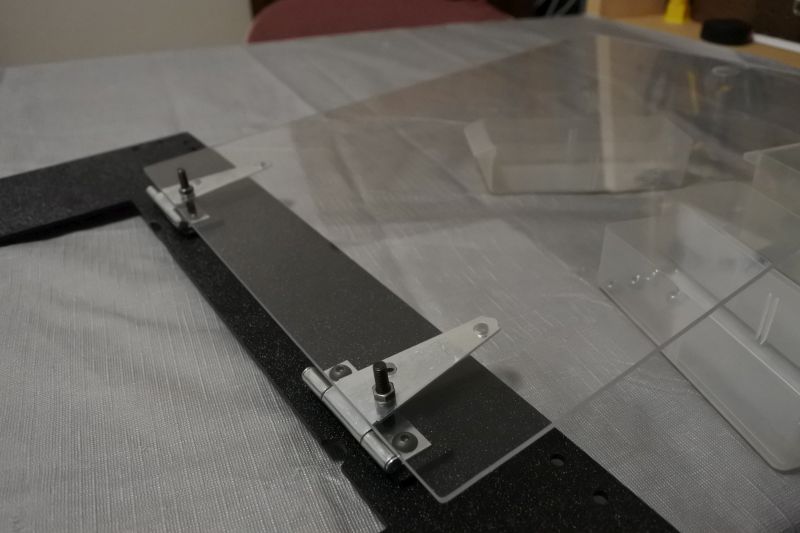
Push an M5 x 16mm Screw through each remaining hinge hole.
Use an M5 Fender Washer and M5 Nut underneath to secure each screw. The fender washers help distribute the load on the relatively brittle acrylic door.
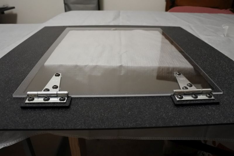
Adjust the Front Door in its screw holes until it is reasonably square with the Front Plate. Then tighten all screws/nuts. The latch for the door will not be added until later. So be careful of it swinging as you work on this piece.
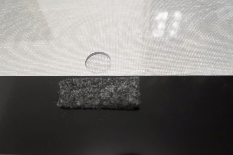
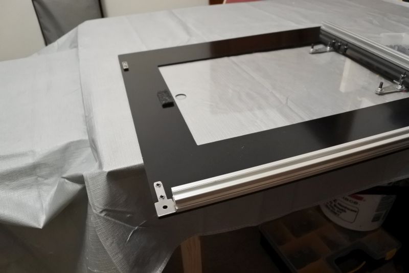
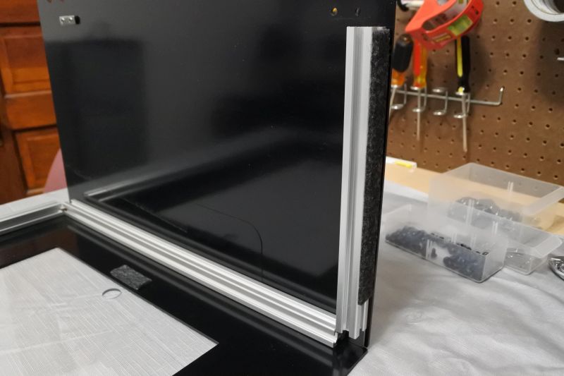
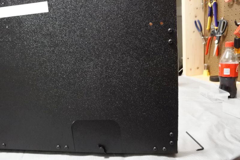
Attach the Short Felt Strip to the back of the Front Plate. It should be centered on the latch hole very close to the inside edge.
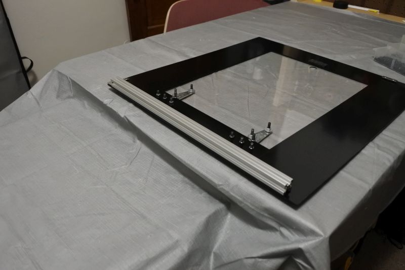
Attach Front Plate
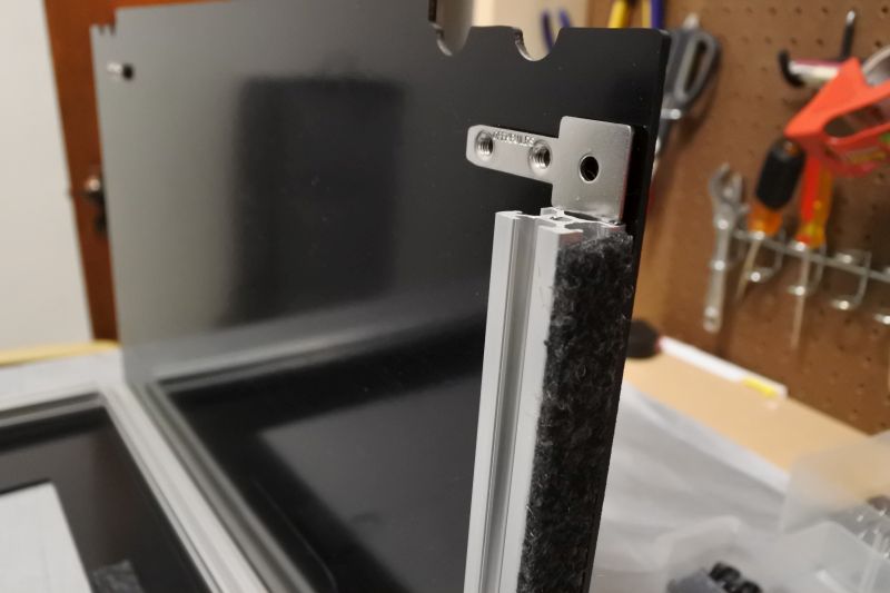
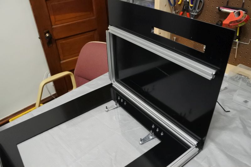
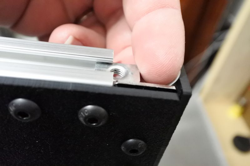
Preload (2) Double T-Nuts on the Front Plate using (4) M5 x 8mm Screws.
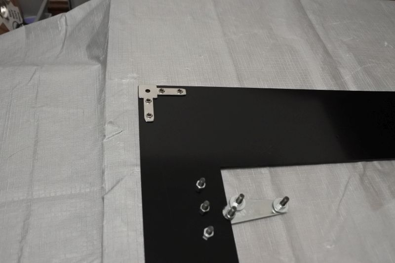
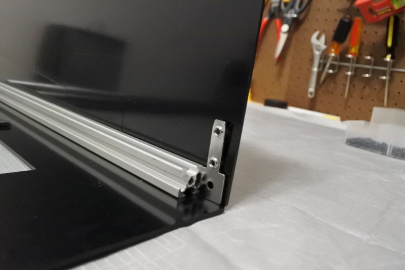
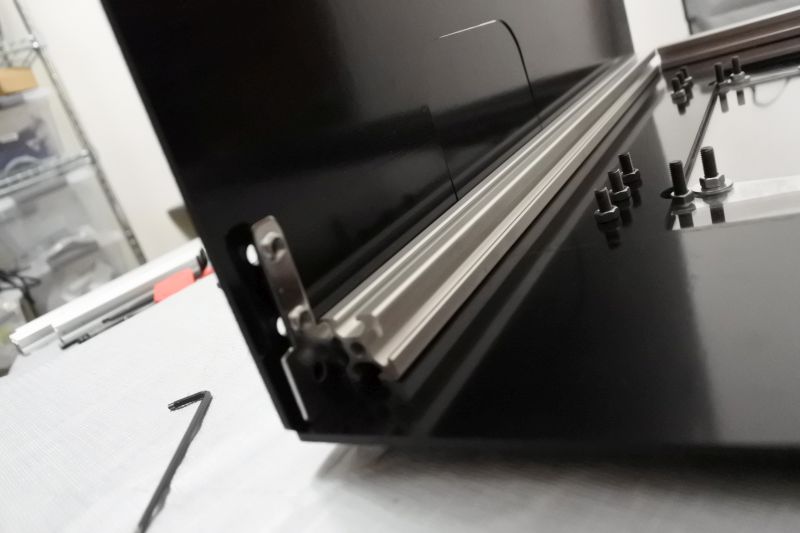
Preload (1) Makerlink 2-Way onto the corner of the Front Plate nearest the hinges using (4) M5 x 8mm Screws.
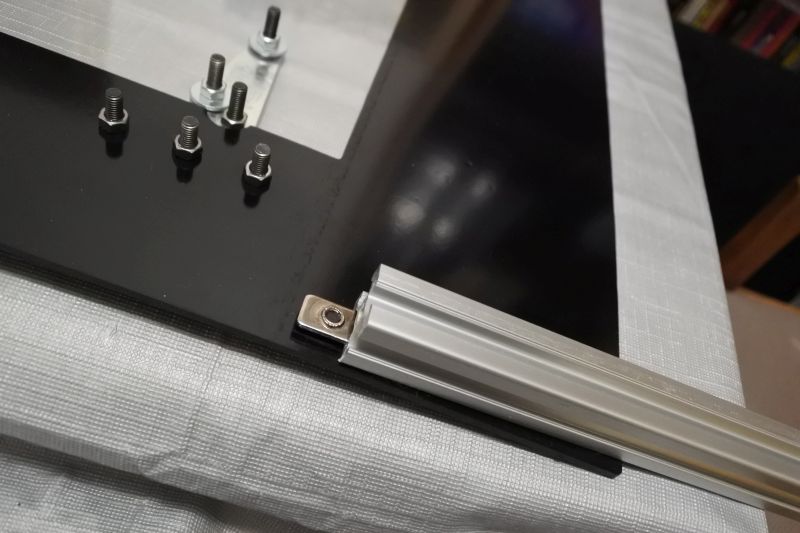
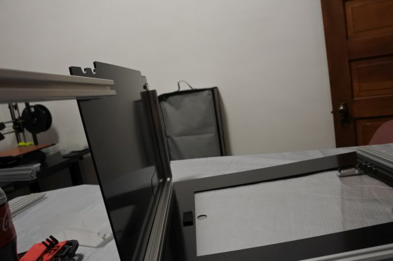
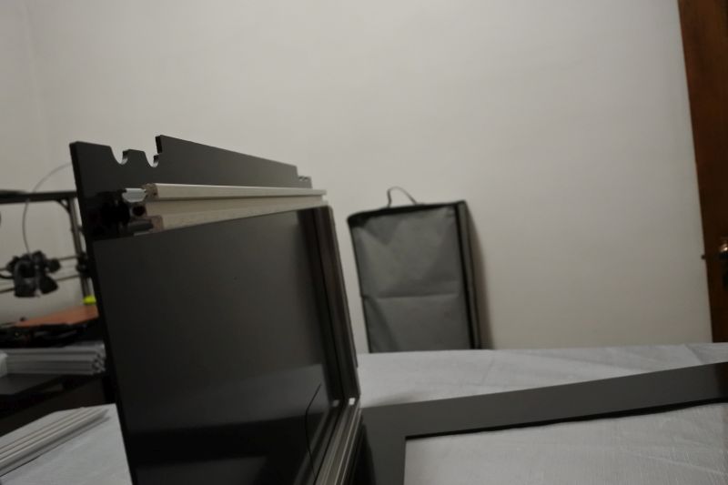
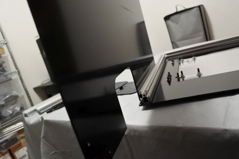
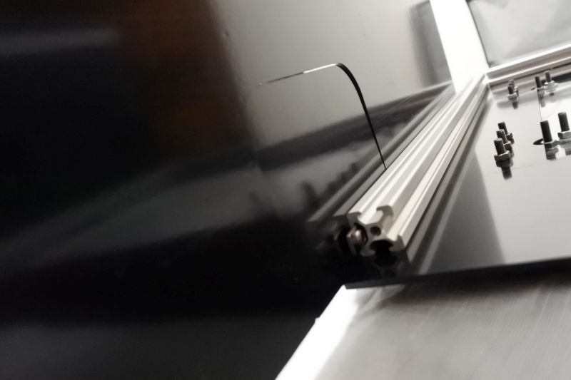
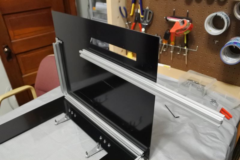
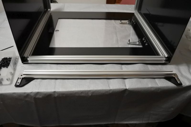
Slide the T-Slot Column onto the side of the Front Plate nearest the hinges. It first slides onto the preloaded Double T-Nut.
Slide the T-Slot Column onto one side of the Makerlink 2-Way. Make sure it is snug against the Makerlink 2-Way and aligned flush with the edge of the Front Plate. Then tighten the screws to secure it into place.
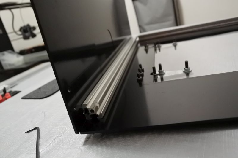
Slide a T-Slot Front Strut onto the other end of the preloaded Makerlink 2-Way. Then add another Makerlink 2-Way into the other end. Use (2) M5 x 8mm Screws to secure the Makerlink 2-Way onto the T-Slot Front Strut. Make sure that the T-Slot Front Strut is flush with the edge of the Front Plate and sandwiched securely between the two Makerlink 2-Ways. Then tighten the screws along this edge.
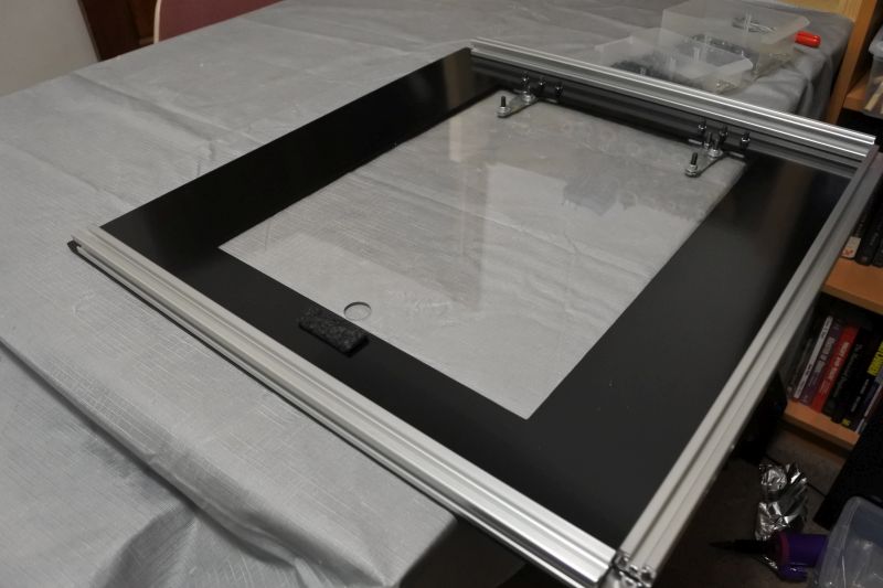
Slide a second T-Slot Column onto the remaining Double T-Nut and Makerlink 2-Way side. Use (2) M5 x 8mm Screws to attach it to the Makerlink 2-Way and then tighten it in place.
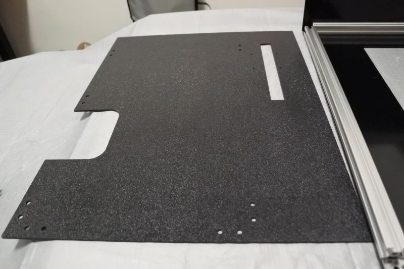
Attach Front-Right Plate
Find the Front-Right Plate.
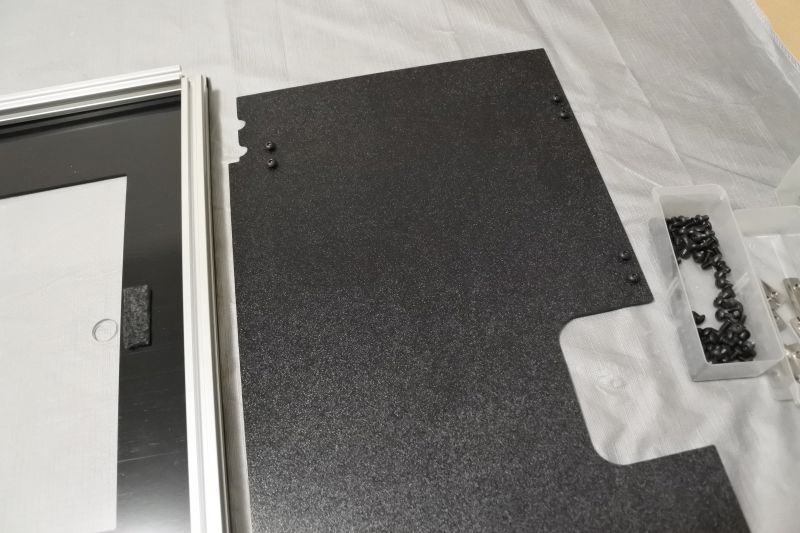
Preload the Front-Right Plate with (3) Double T-Nuts and (6) M5 x 8mm Screws.
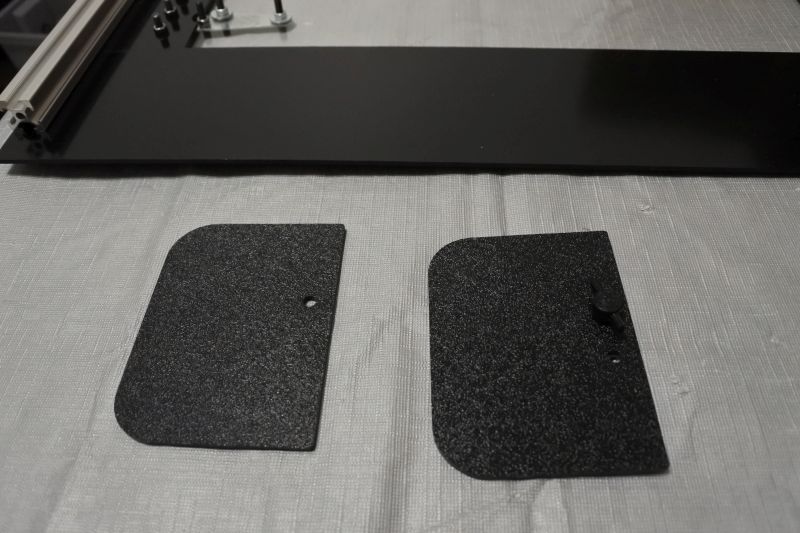
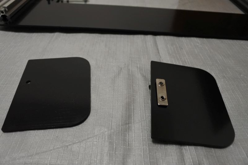
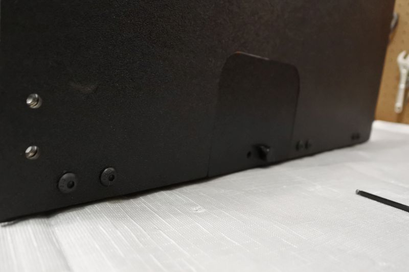
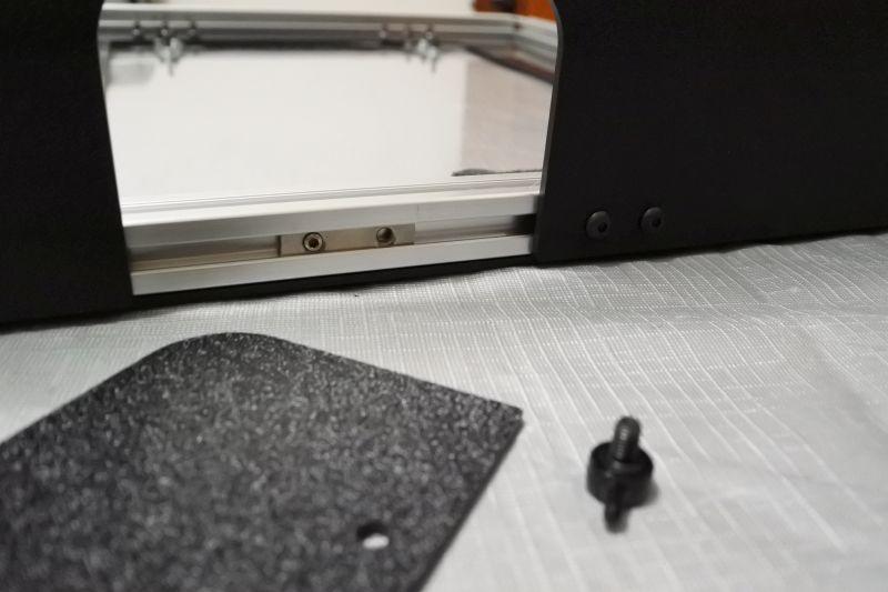
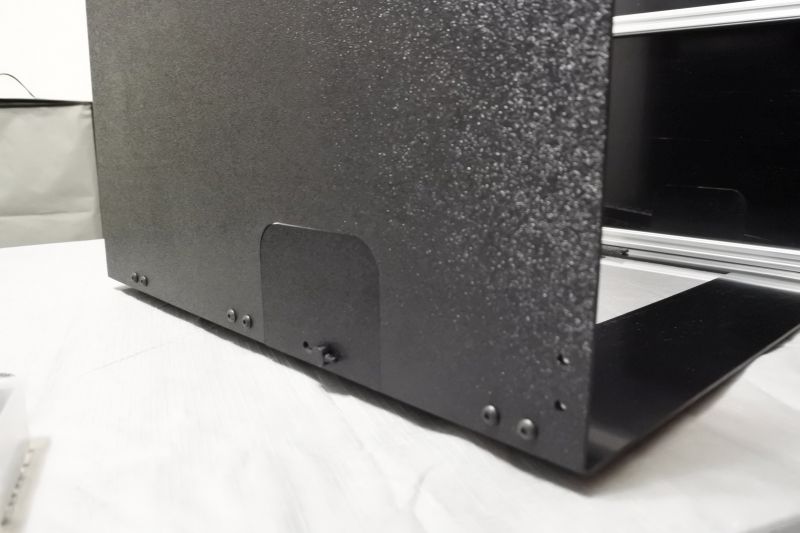
Find a Handle Cover and Handle Cover Template. Preload the Handle Cover Template (which has two holes) using a Double T-Nut and an Thumb Screw. Make sure that the Thumb Screw is attached via the hole on the same side as the Handle Cover and that the other hole on the Hanlde Cover Template is aligned with the second hole on the Double T-Nut. The purpose of this is to let us permanently fix the Double T-Nut into place with a Set Screw so that we can easily attach and detach the Handle Cover later on.
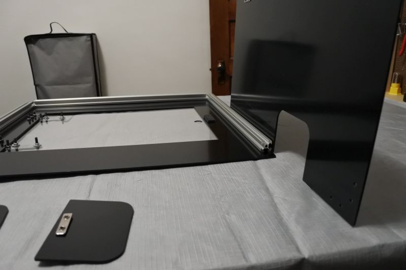
Begin sliding the Front-Right Plate onto the T-Slot Column nearest the door latch. Stop when you get to the rounded square cutout.
Place the Handle Cover Template into the rounded cutout and continue sliding. Make sure that the preloaded Double T-Nut goes into the slot and is facing the correct direction.
Finish slidingthe Front-Right Plate onto the T-Slot Column.
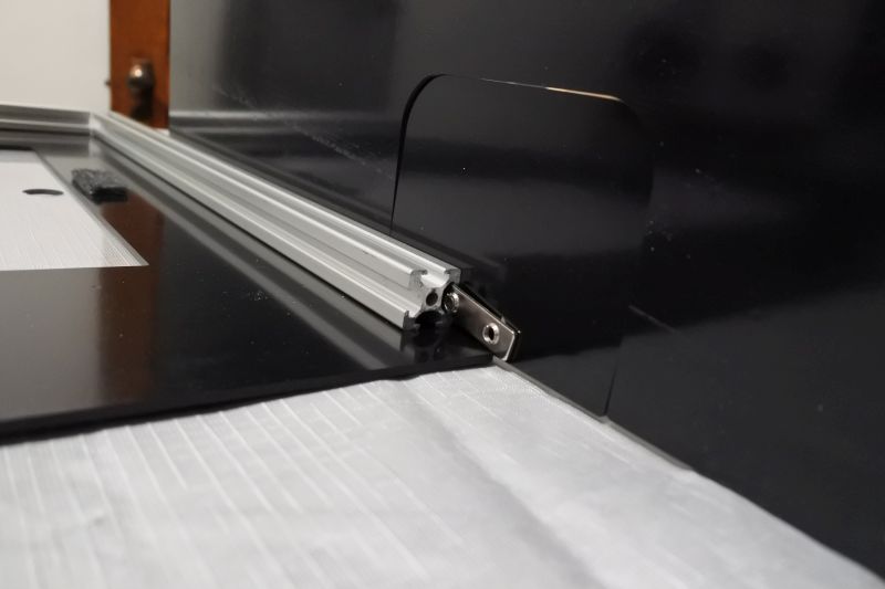
Slide Makerlink 2-Way onto the end of the T-Slot Column. Move the Front-Right plate so that the holes line up with the Makerlink 2-Way.
Attach the Makerlink 2-Way with (2) M5 x 8mm Screws. Make sure the T-Slot Column is aligned along the bottom of the Front-Right Plate and that both ends of the MakerLink sandwich the T-Slot Column snugly. Then tighten up all screws on this edge.
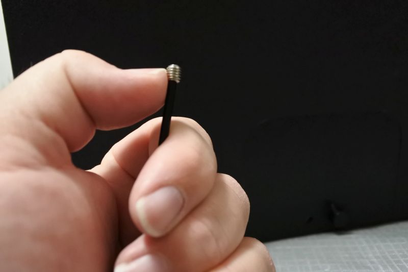
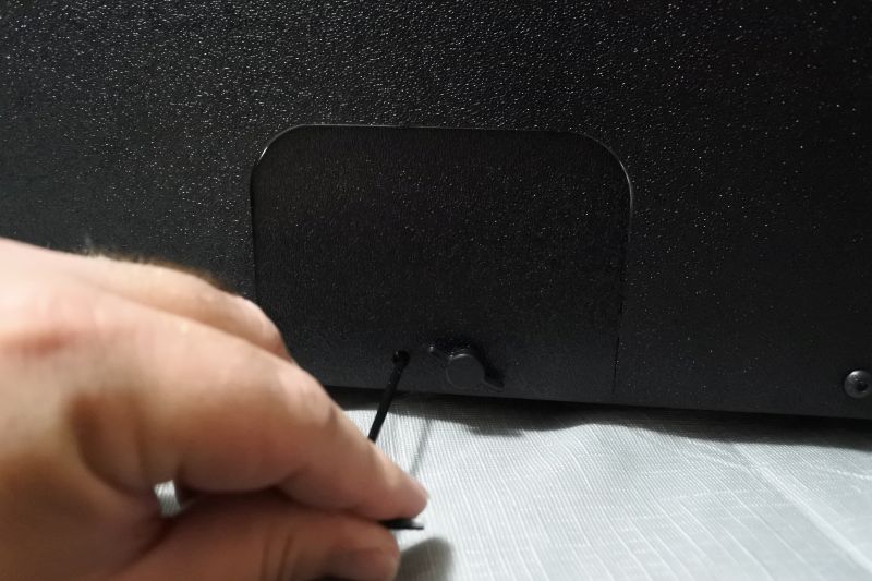
Get a Set Screw on the end of a 2.5mm Hex Key.
Screw in Set Screw on the unused hole of the Handle Cover Template. This will keep the Double T-Nut in place whether or not it is secured by a Thumb Screw.
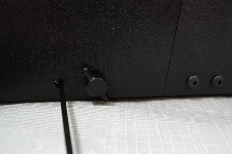
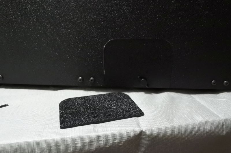
Unscrew the Thumb Screw and remove the Handle Cover Template.
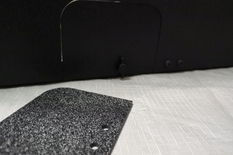
Attach a Handle Cover using the Thumb Screw. Set aside the Handle Cover Template for use later.
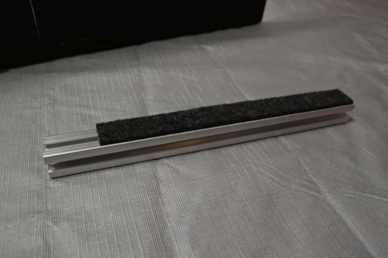
Attach (1) Long Felt Strip to one side of (1) T-Slot Front Base. Repeat for the other T-Slot Front Base.
Slide (1) T-Slot Front Base onto the end of the Makerlink 2-Way with the Felt Strip pointed outward.
Slide (1) Makerlink 2-Way onto the other end of the T-Slot Front Base.
Attach (2) M5 x 8mm Screws to the Makerlink 2-Way and T-Slot Front Base. The felt strip of the front base should stick out slightly from the bottom of the Front-Right plate to help ensure that the Front-Right Plate never scrapes the table. Keep it aligned straight along the edge and sandwiched securely between the Makerlink 2-Ways it sits on. Tighten all screws along this edge.
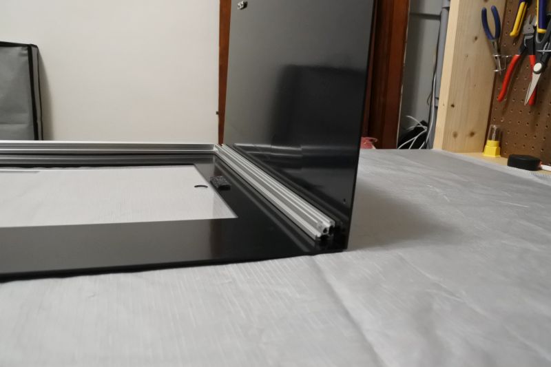
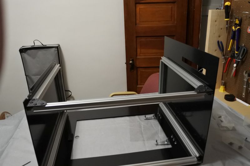
Turn the assembly around and slide in a T-Slot Column along the third edge of the Front-Right Plate opposite the T-Slot Front Base.
Rest the T-Slot Column snugly against the remaining side of the Makerlink 2-Way. Attachit wit (2) M5 x 8mm Screws. Tighten all screws along this edge.
Attach Front-Left Plate
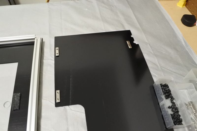
Find the Front-Left Plate.
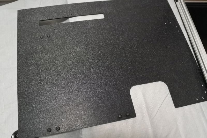
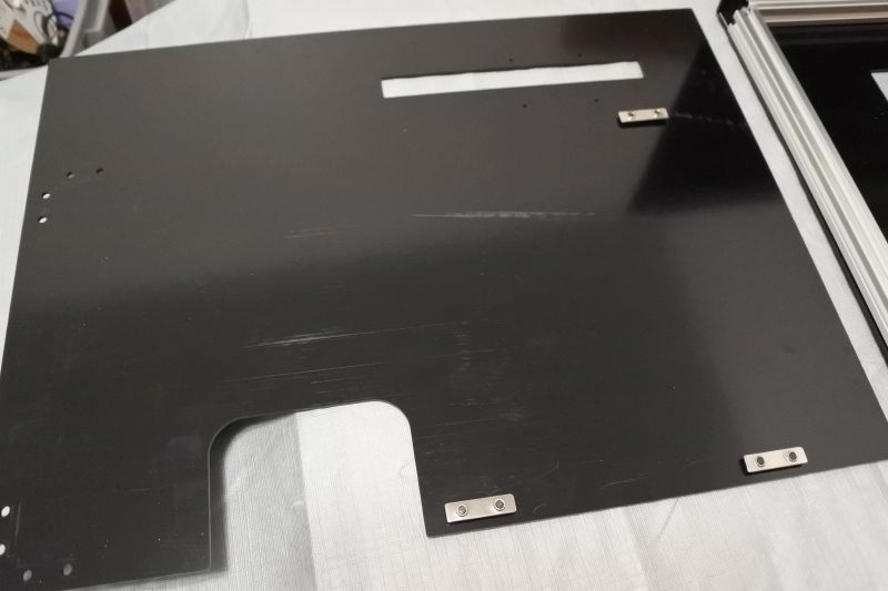
Preload the Front-Left Plate with (3) Double T-Nuts and (6) M5 x 8mm Screws.
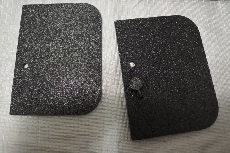
Preload Handle Cover Template making sure to use the thumb screw in the hole on the same side as a Handle Cover has.
Slide Front-Left Plate onto T-Slot Column near the hinges.
Slide Handle Cover Template onto T-Slot column along with Front-Left Plate.
Finish sliding Front-Left Plate on.
Add Makerlink 2-Way onto the end of the T-Slot Column.
Attach Front-Left Plate to Makerlink 2-Way using (2) M5 x 8mm Screws. Tighten all screws along this edge.
Attach (1) Set Screw using the hole in the Handle Cover Template.
Replace Handle Cover Template with Handle Cover. Set aside Handle Cover Template for later use.
Slide T-Slot Front Base onto the end of Makerlink 2-Way with felt strip pointed outward. Add another Makerlink 2-Way onto the other end.
Screw in (4) M5 x 8mm Screws along this edge. Ensure the T-Slot Front Base is aligned and snug between the Makerlink 2-Way then tighten all screws along this edge.
Slide T-Slot Column onto the opposite side of the Front-Left Plate.
Slide T-Slot Column onto the free end of the Makerlink 2-Way.
Use (2) M5 x 8mm Screws to attach the T-Slot Column using the remaining holes. Tighten all screws along this edge.
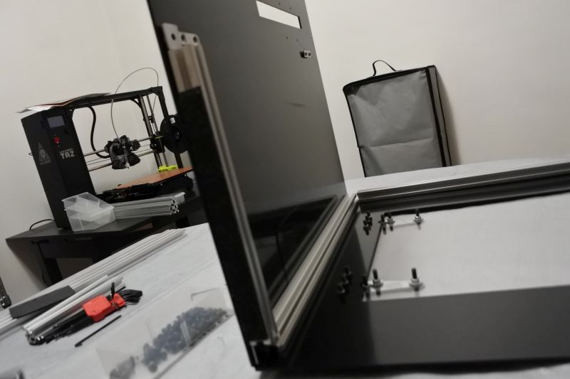
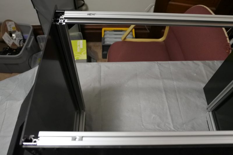
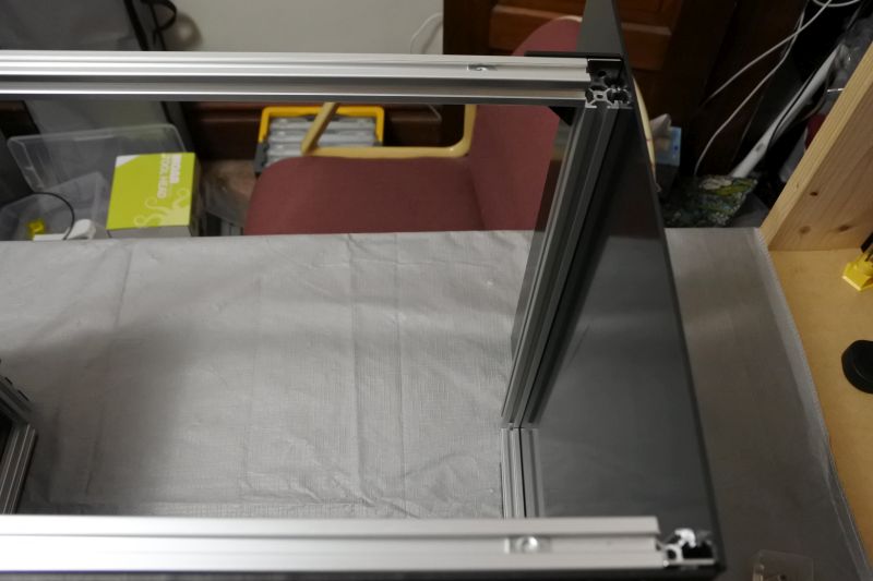
Complete Front Structure
Preload Makerlink 2-Way onto each of (2) Corner Brackets.
Slide the Makerlink 2-Way onto each end of a T-Slot Front Strut.
Slide the other ends of the MakerLink 2-Way onto the two free ends of the T-Slot Columns.
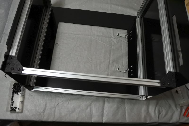
Make the T-Slot Front Strut snug between the Makerlink 2-Ways and then tighten all screws.
Install Cam Latch
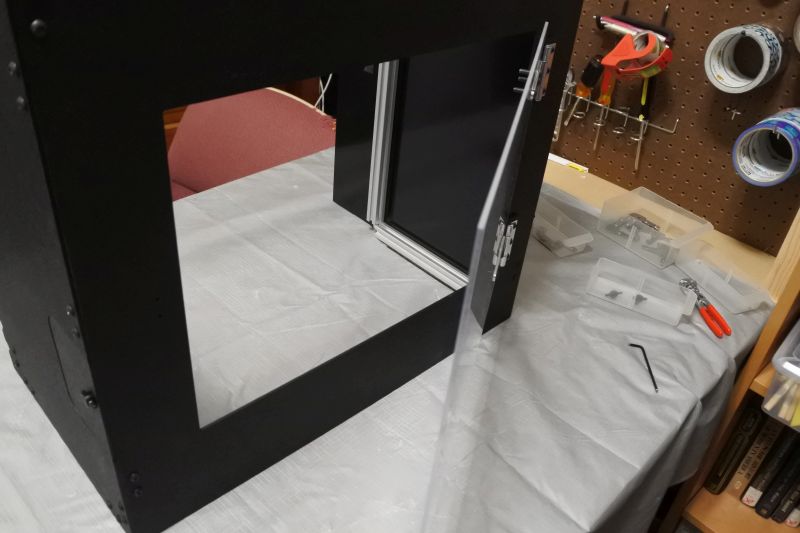
Turn Front Enclosure upright. The door should freely swing open.
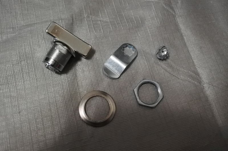
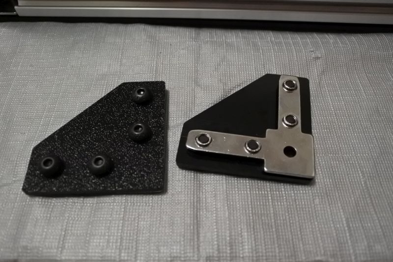
Find the Cam Latch. There are a couple of unused pieces in the bag. Shown are the pieces you will need to use for this project.
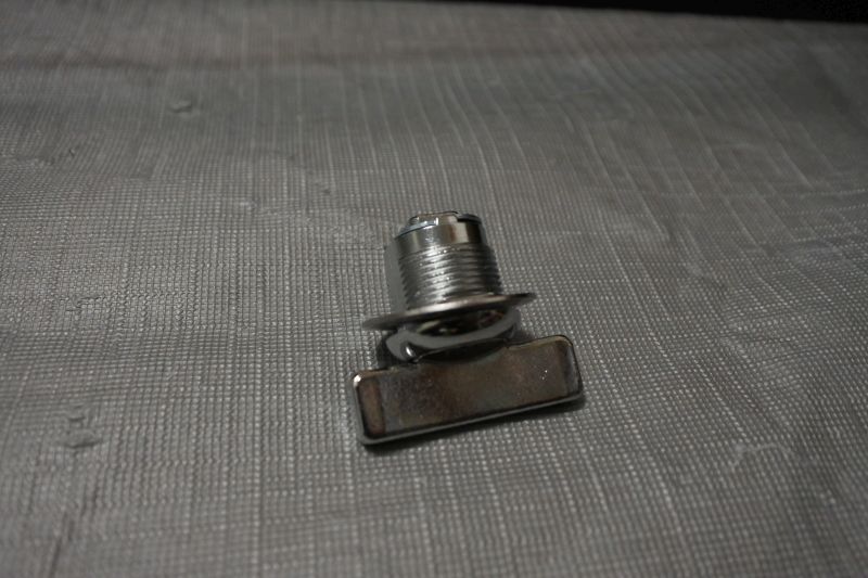
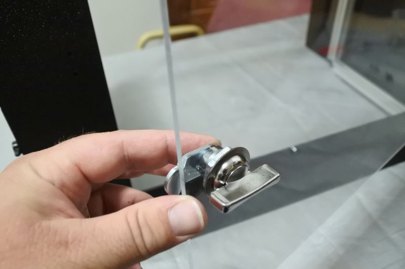
Put the large flare washer on the wing base. Make sure that the flared portion faces up.
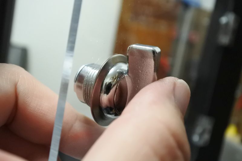
Push the wing base through the cutout on the Front Door. The flared portion of the washer should press against the acrylic.
Screw the large nut onto the wing base on the other side of the Front Door. This will hold it in place.
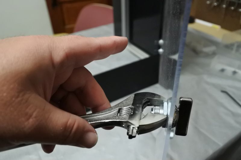
Use a wrench to tighten the large nut.
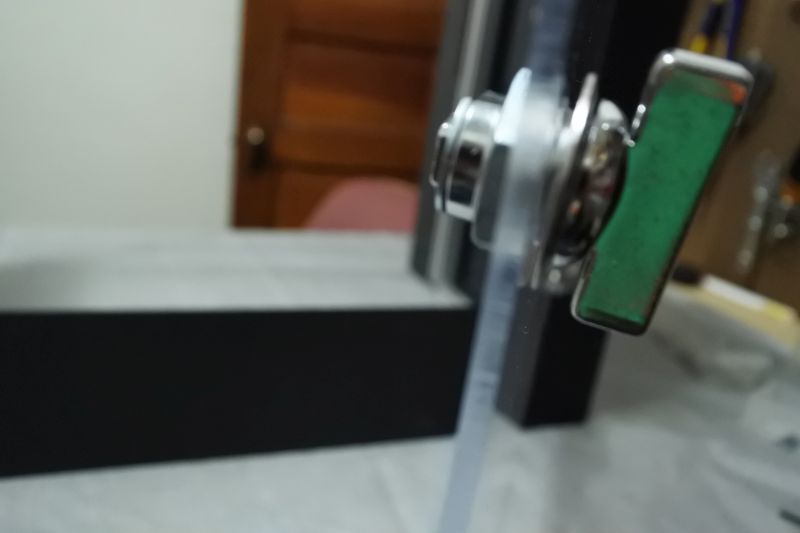
Put the bent plate on the wing base so that the bend is towards the Front Door. The bent plate can only attach in one of four orientations. Based on the orientation of the bent plate and the wing, you can choose which direction will latch or unlatch the door.
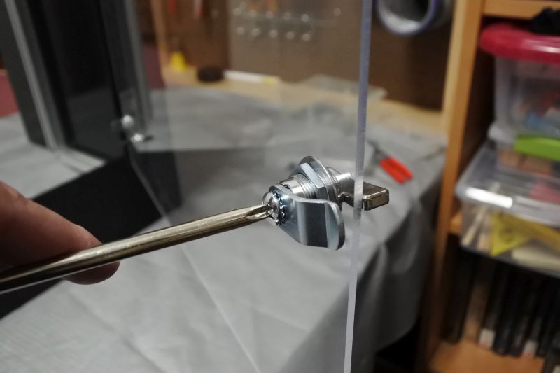
The bent plate is held onto the wing base by a screw. Once you have it in the position you want, hold it and screw it in place.
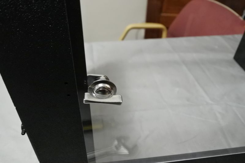
The Cam Latch is now complete. Leave the door latched for the remainder of the assembly.
Attach Front-Top Plate
Add (4) Single T-Nuts to the top of the assembly. One Single T-Nut should be near each corner at the top.
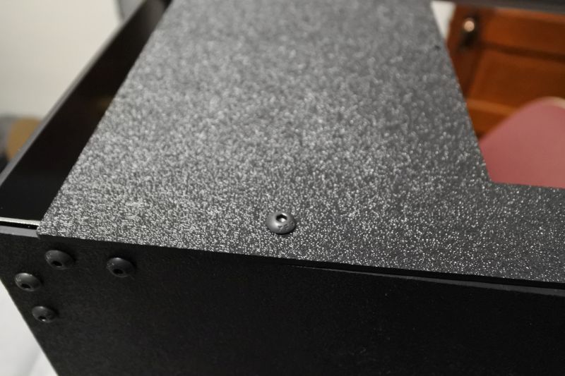
Find the Front-Top Plate. Use an M5 x 8mm Screw to attach each of the four mounting holes to a Single T-Nut. To do this, yo uwill be moving the plate around, moving the nuts around, and only very loosely attaching each nut as you get to it. Only once all four nuts are loosely attached will you align it to the top edges of the other pieces and tighten all four nuts.

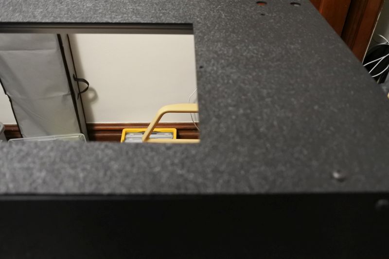
Find the Top-Front Window. Place it on the Top-Front Plate aligned with the two small holes.

Screw in the Top-Front Window with (2) M3 x 14mm Screws and (2) M3 Nuts.
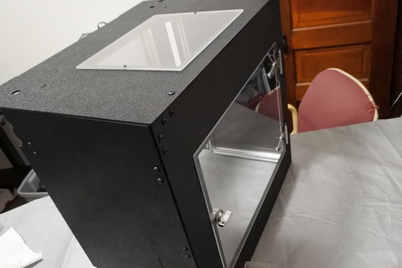
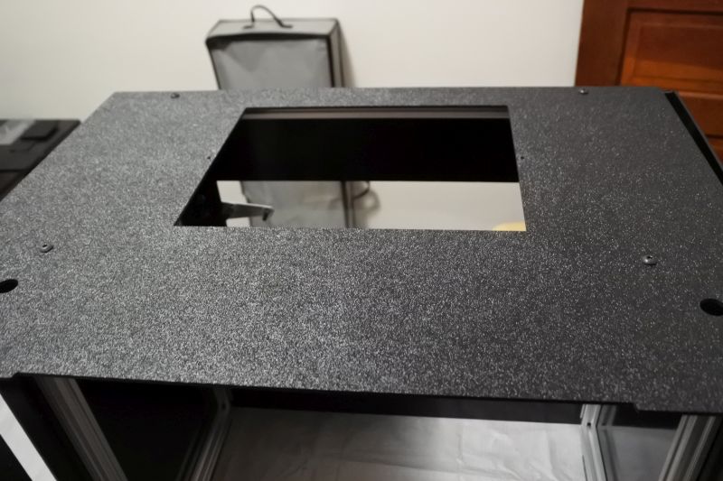
Completed Front Enclosure

The Front Enclosure is now complete. Continue to Back Enclosure Assembly.