Cradle Base Assembly
Special Notes
M5 Washers and 1.00mm Spacers look very similar. Do not mix them up.
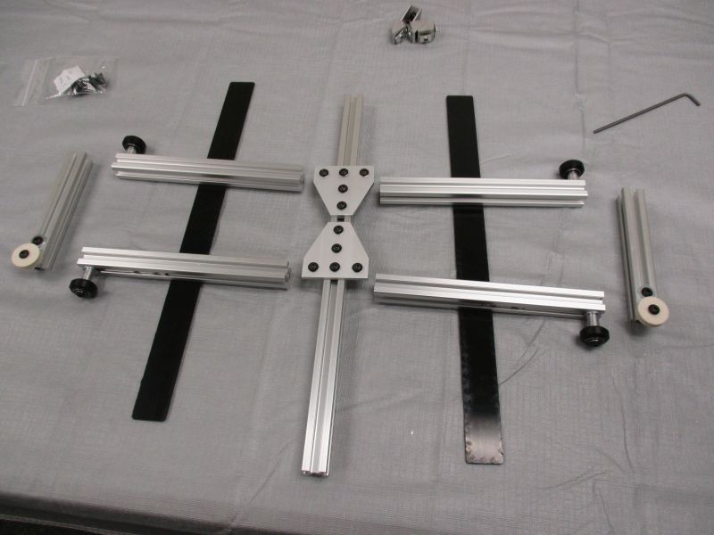
Inventory
Tools needed:
- 3mm Hex Key (in Tool Bag)
Parts needed:
- (1) Cradle Base Assembly Bag
- (2) Cradle Base Cover
- (1) Cradle Base Beam
- (2) Base Side Beam
- (4) Base Strut
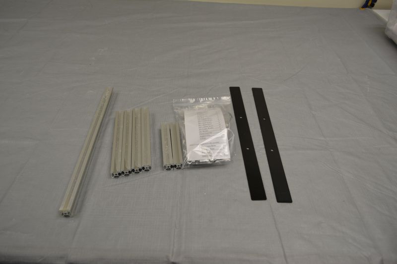
Gather parts together and remove plastic coating from extrusion pieces if necessary. Use the part list in the Cradle Base Assembly Bag to verify that all parts are present before beginning. Notify help@tenrec.builders if any parts are missing.
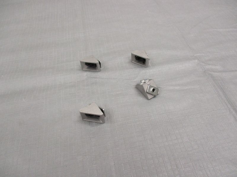
Preload (4) Corner Brackets.
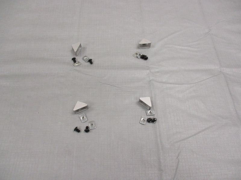
Each Corner Bracket uses (2) M5 x 8mm Screws and (2) Single T-Nuts.
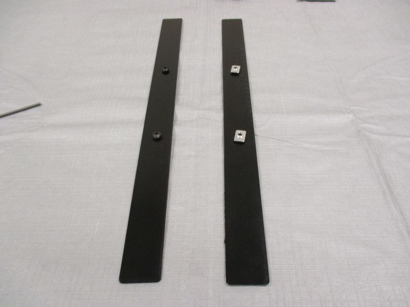
Preload (2) T-Plates
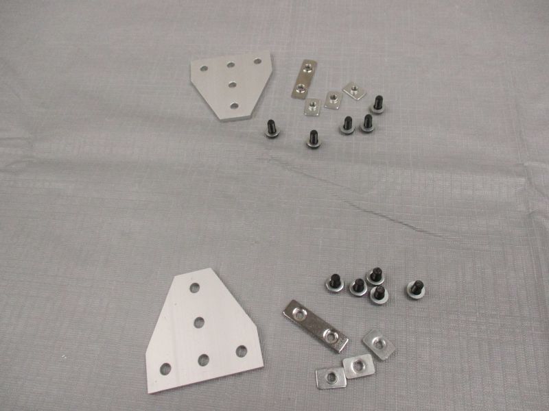
Each T-Plate uses (5) M5 x 10mm Screws, (5) M5 Washers, (1) Double T-Nut, and (3) Single T-Nuts.
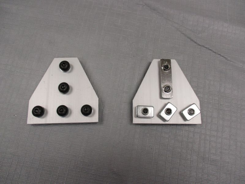
Place washers on screws. Preload according to picture.
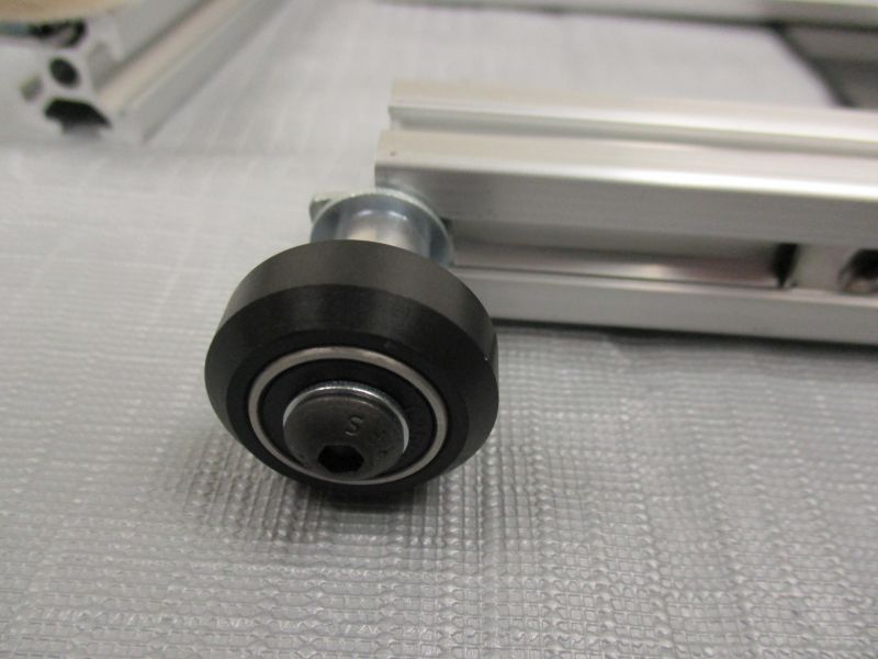
Assemble (4) V-Wheels
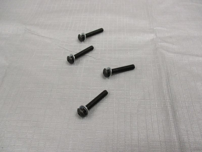
Take 4 M5 x 30mm Screws and place an M5 Washer on each screw. This will help avoid mixups in the following steps.
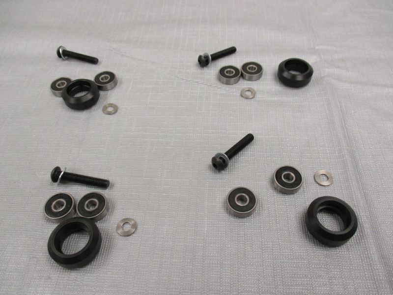
Each V-Wheel uses (1) M5 x 30mm Screw with attached M5 Washer, (2) Bearings, and (1) 1.00mm Spacer.
For each set, place items in the following order on the M5 x 30mm Screw: M5 Washer -- (1) Bearing -- V-Wheel -- 1.00mm Spacer -- (1) Bearing
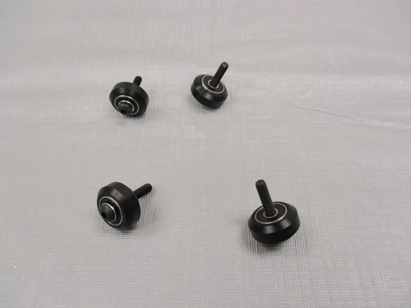
Squeeze this sandwich together, pressing the (2) Bearings into the sides of the V-Wheel. For a more detailed explanation of assembling V-Wheels, see the Cradle Lifter Assembly Guide.
Preload (4) V-Wheels
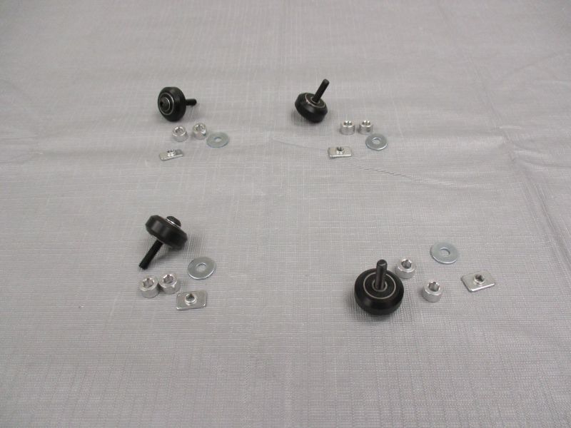
Each V-Wheel uses (2) 6.35mm Spacers, (1) M5 Fender Washer, and (1) Single T-Nut.
Put (2) 6.35mm Spacers on each Assembled V-Wheel.
Put (1) M5 Fender Washer on each Assembled V-Wheel.
Thread (1) Single T-Nut on each Assembled V-Wheel.
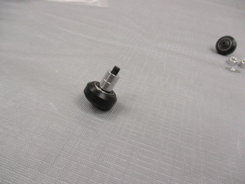
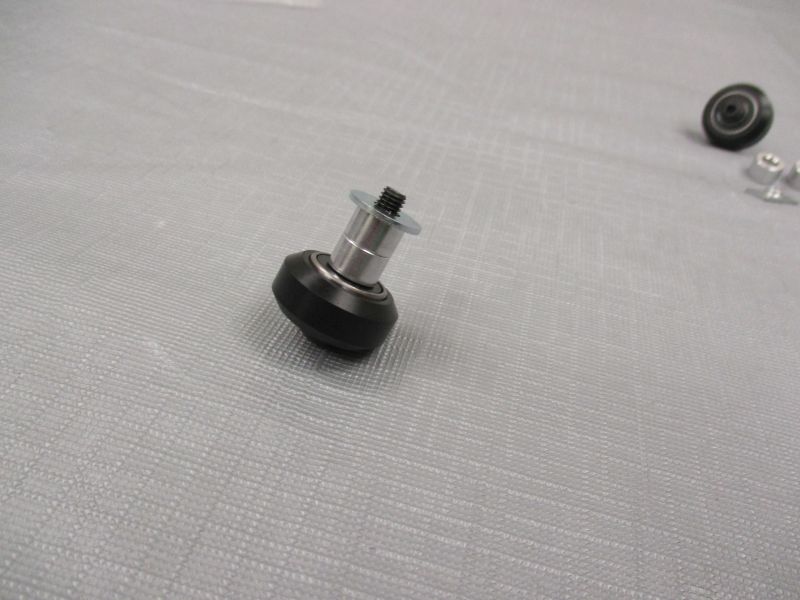
Hold the Single T-Nut with your fingers and use a 3mm Hex Key to tighten the assembly. This will finish pressing the bearings into the wheels.
Loosen the Single T-Nut again. A gap between the M5 Fender Washer and the Single T-Nut will be necessary to insert it into an extrusion slot.
Preload (2) Base Covers
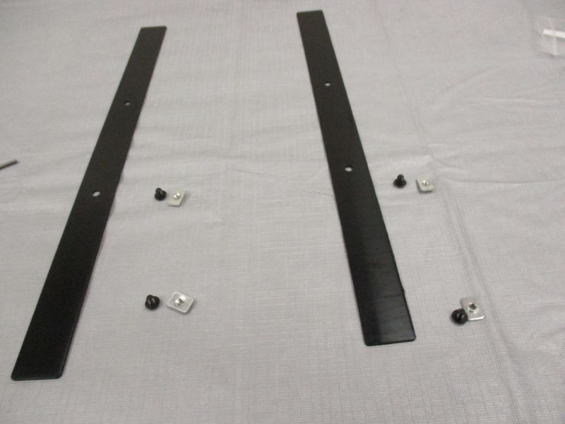
Each Base Cover uses (2) M5 x 6mm Screws and (2) Single T-Nuts.
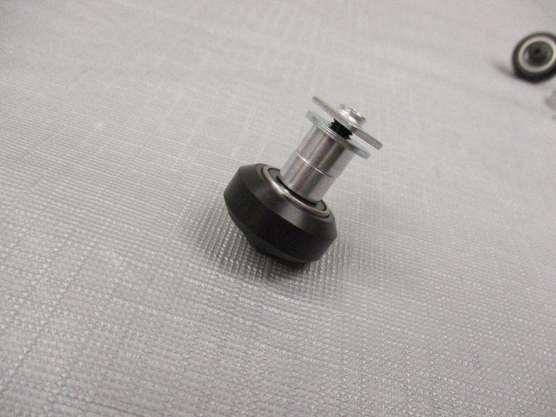
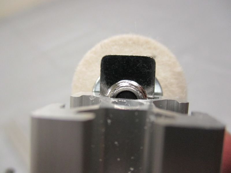
Preload (2) Felt Bobs
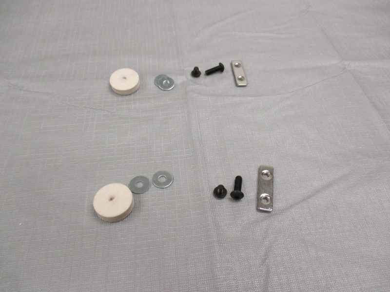
Each Felt Bob uses (1) M5 x 6mm Screw, (2) M5 Fender Washers, (1) M5 x 16mm Screw, and (1) Double T-Nut.
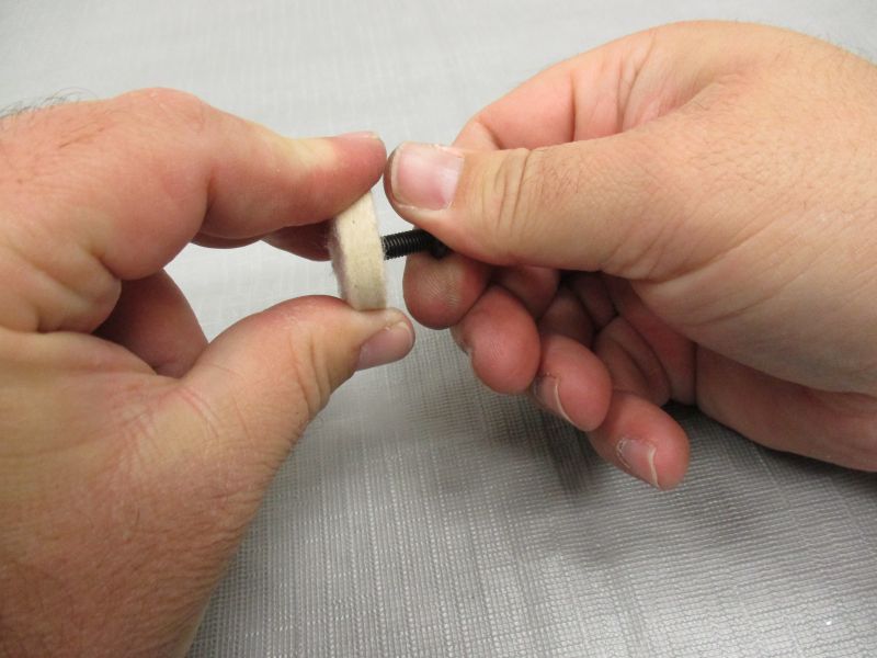
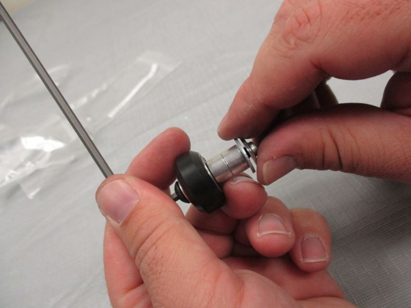
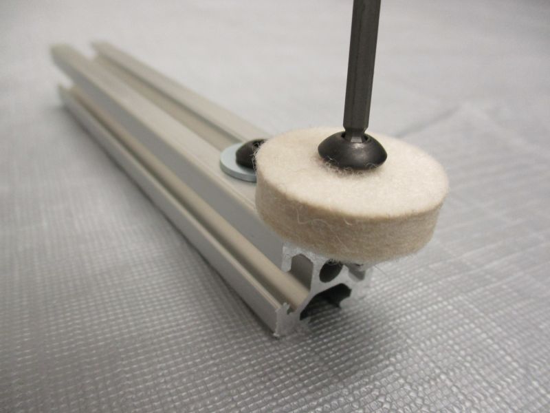
Screw an M5 x 16mm Screw into the center of each Felt Bob. The hole is just barely big enough, so push while turning the screw with your fingers.
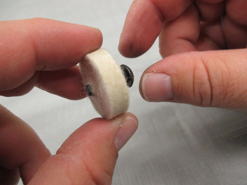
Once the M5 x 16mm Screw is deeper into the material, friction will increase too much for finger tightening.
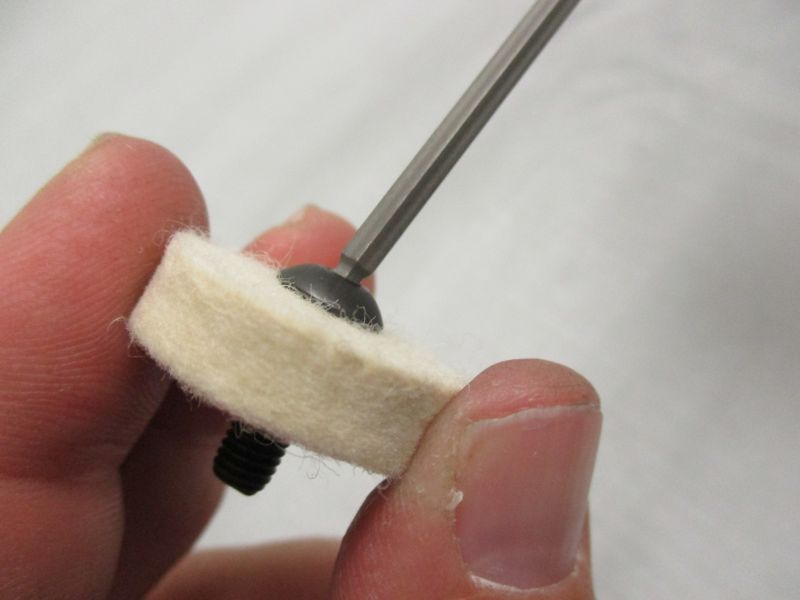
Use the 3mm Hex Key to keep turning the M5 x 16mm Screw until it is completely seated in the Felt Bob.
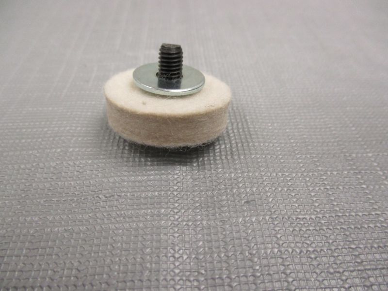
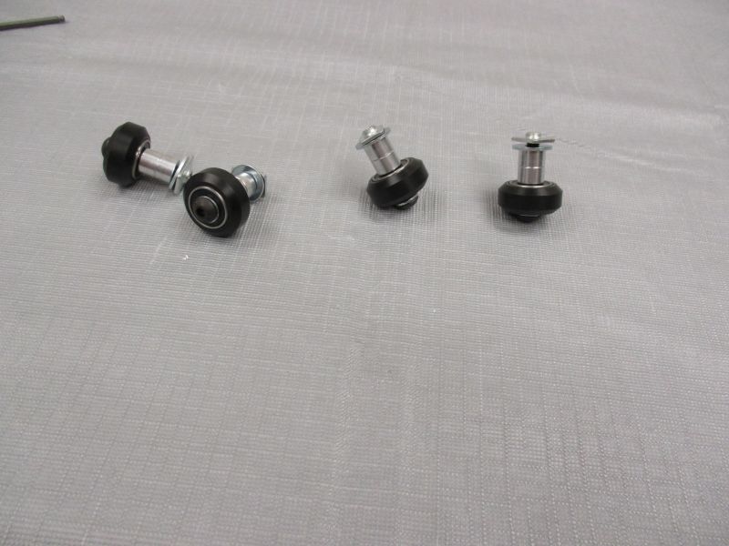
Place M5 Fender Washer on the Felt Bob.
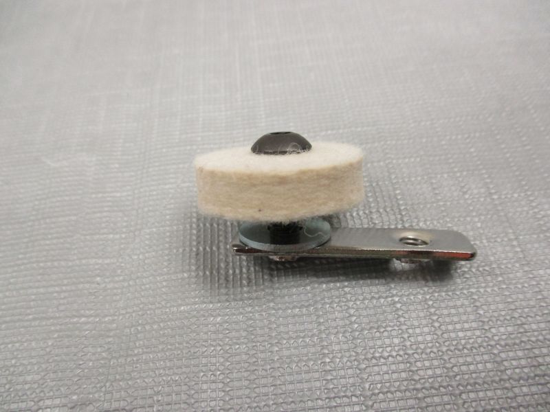
Screw Felt Bob onto one side of a Double T-Nut.
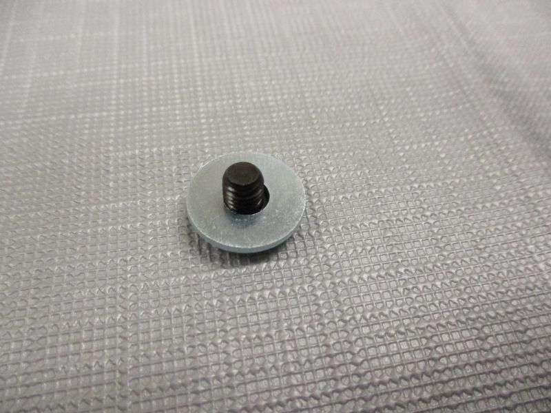
Place M5 Fender Washer on the M5 x 6mm Screw.
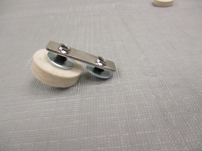
Screw M5 x 6mm Screw into the other side of Double T-Nut.
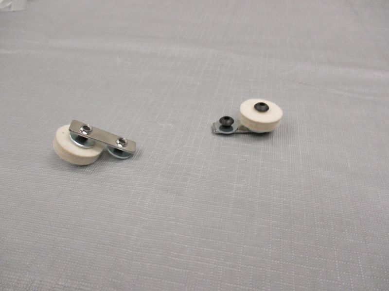
Complete the other Felt Bob Assembly.
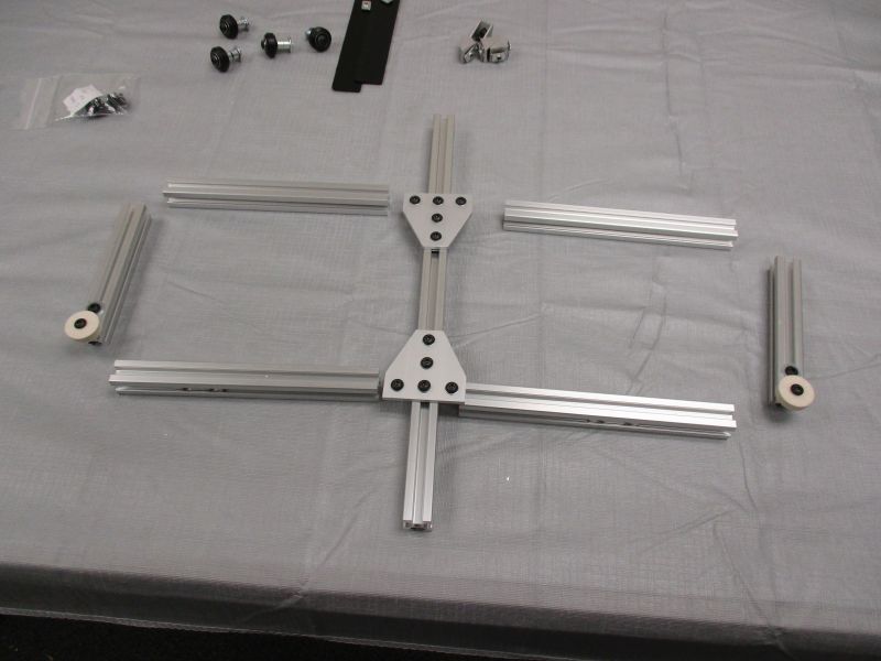
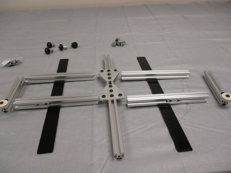
Assemble Base
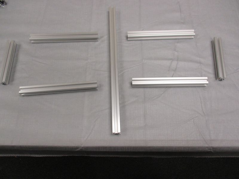
Gather (1) Base Center Beam, (2) Base Side Beams, and (4) Base Struts.
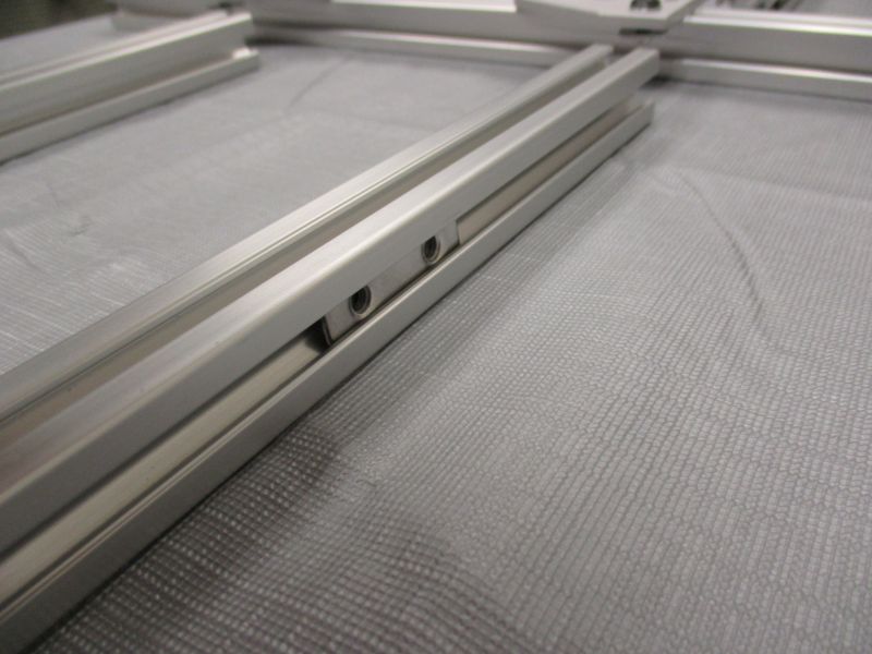
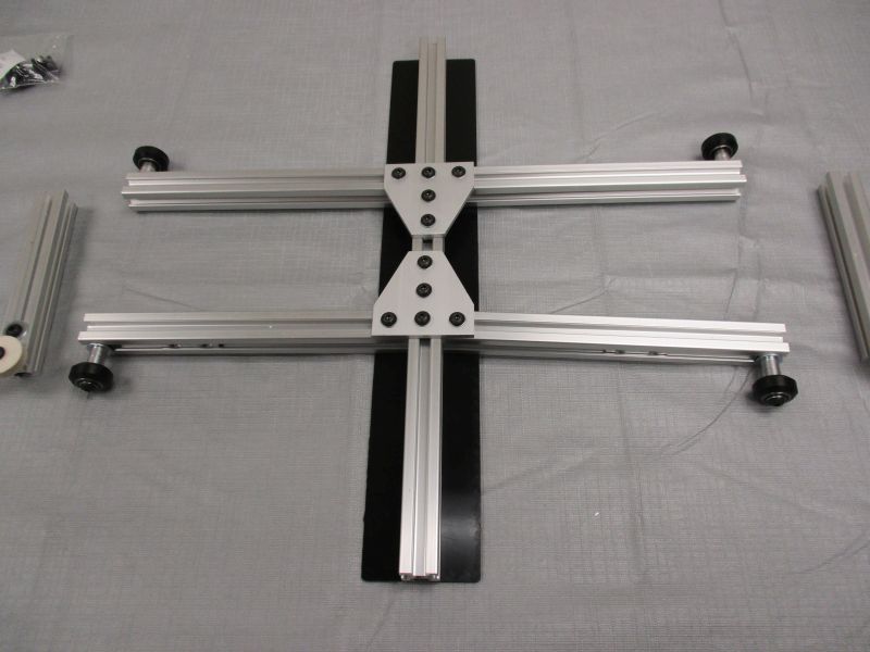
Slide a T-Plate Assembly onto one end of the Base Center Beam.
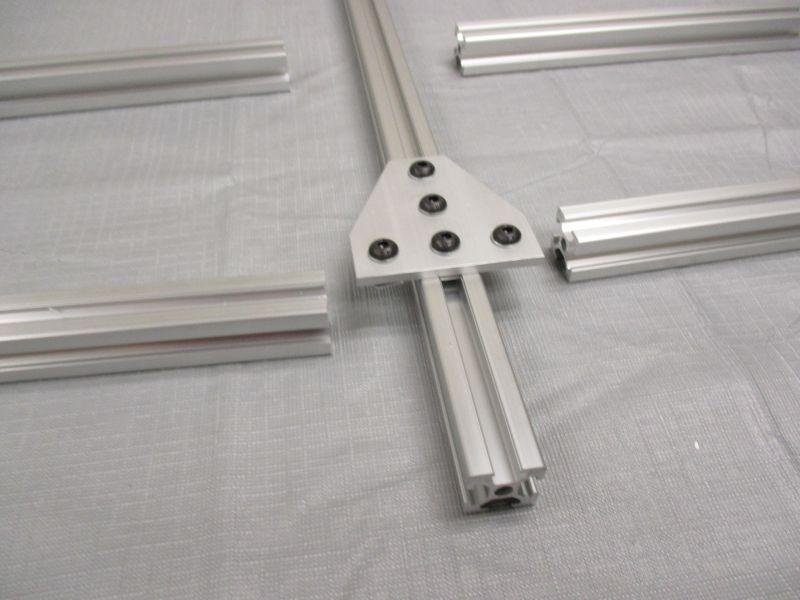
The long leg of the T-Plate faces towards the middle of the Base Center Beam.
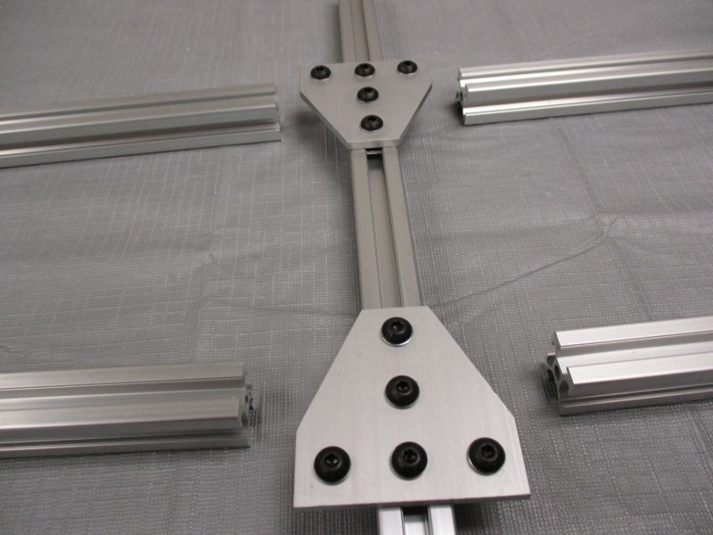
Slide the other T-Plate onto the Base Center Beam facing the opposite direction.
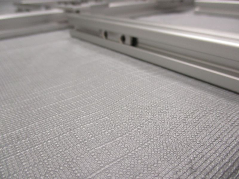
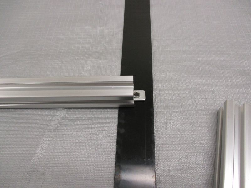
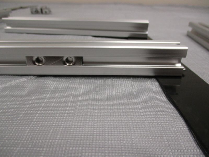
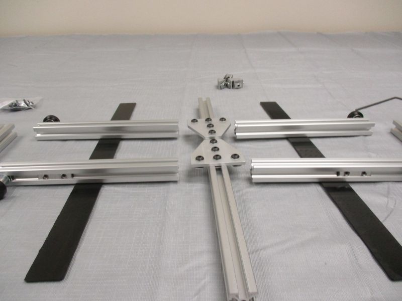
Gather (4) Double T-Nuts. Slide a Double T-Nut into outward-facing slot of each Base Strut. Make sure the bumps of the Double T-Nuts face towards the center of the beam with the flat side facing outwards.
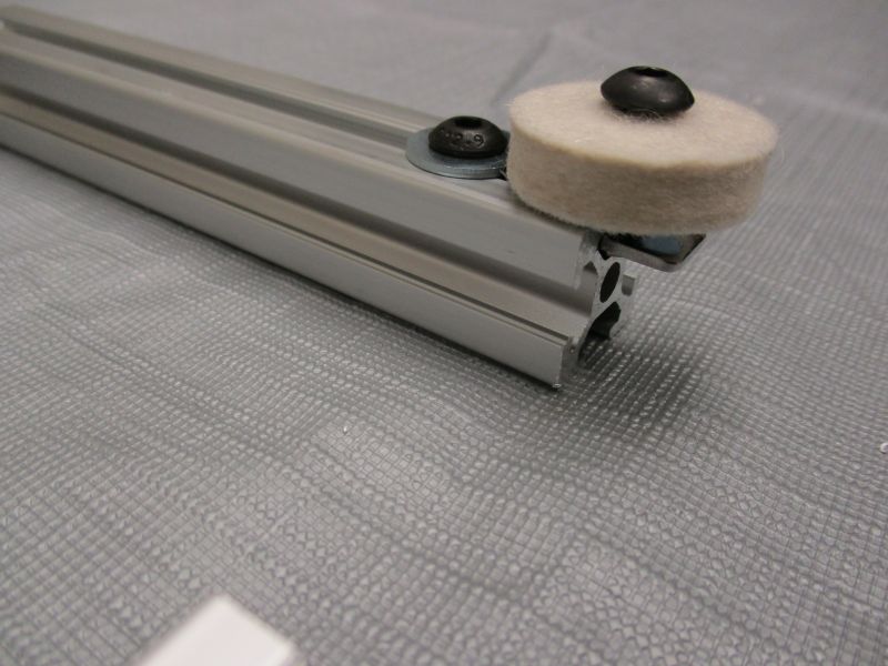
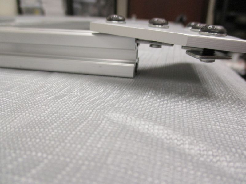
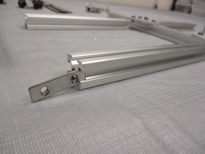
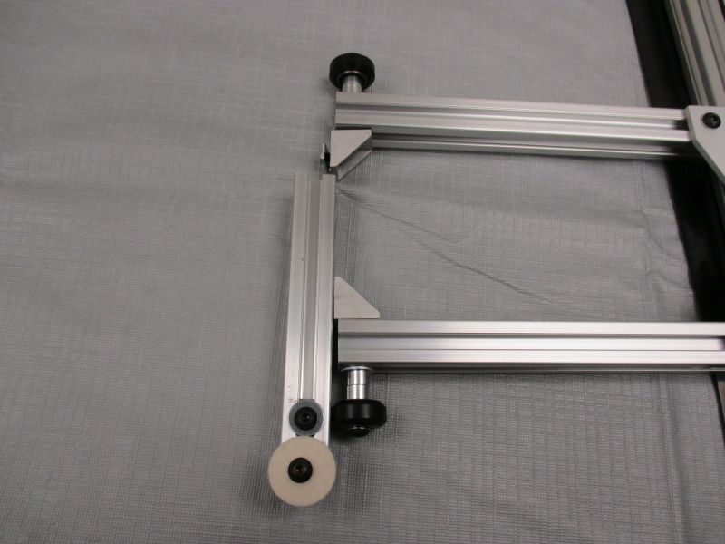
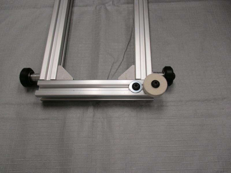
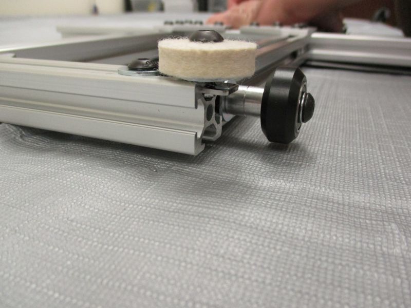
Gather (2) Felt Bob Assemblies. Slide one onto each Base Side Beam.
Snug both screws with Felt Bob sticking out from the end of the Base Side Beam. The position of the Felt Bob will need to be adjusted later.
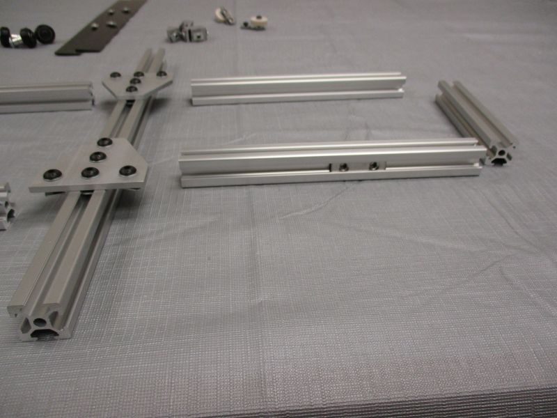
Overview with Double T-Nuts and Felt Bobs inserted.
Slide a Base Cover onto the bottom slot of a Base Strut on.
Slide the Base Cover onto the bottom slot of the other Base Strut on the same side.
Slide the other Base Cover onto the bottom slots of the opposite pair of Base Struts.
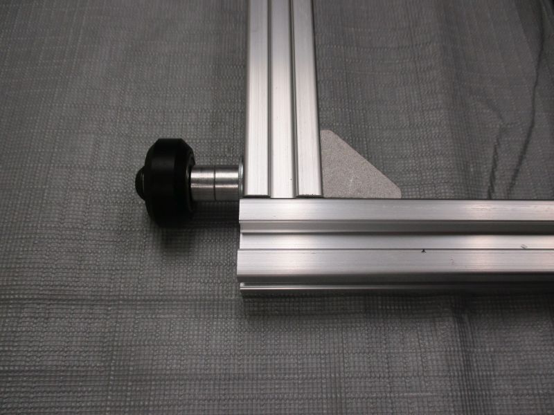
Slide a V-Wheel Assembly onto the outside slot of one of the Base Struts.
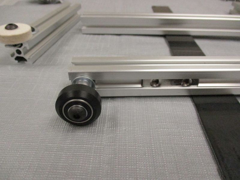
The V-Wheel Assembly should be far enough in that the M5 Fender Washer does not stick out. Precise positioning is not important. Snug screw into place.
Repeat for the other Base Struts and V-Wheel Assemblies. There will be a V-Wheel at each corner.
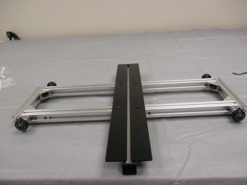
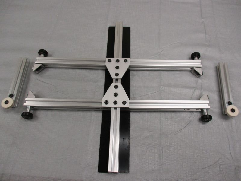
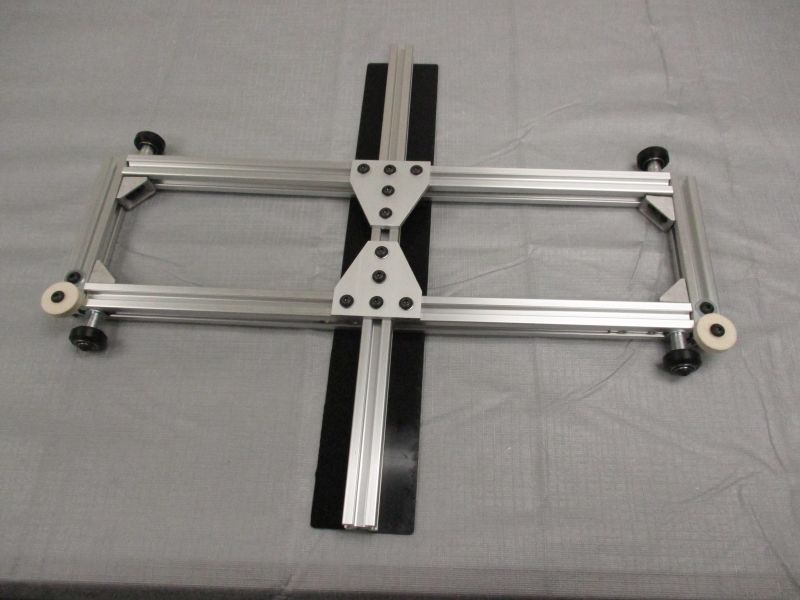
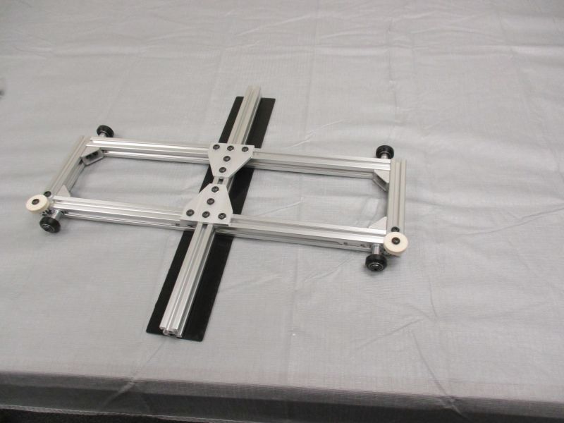
Overview with Base Covers and V-Wheels inserted.
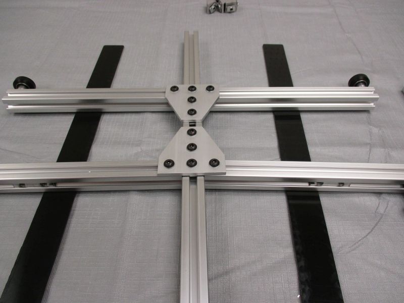
Slide (4) Base Struts onto the (2) T-Plates in the center.
Slide Base Covers towards the center. The Base Covers determine how far apart the T-Plates are from one another. Snug all T-plate screws with the Base Struts connecting at right angles.
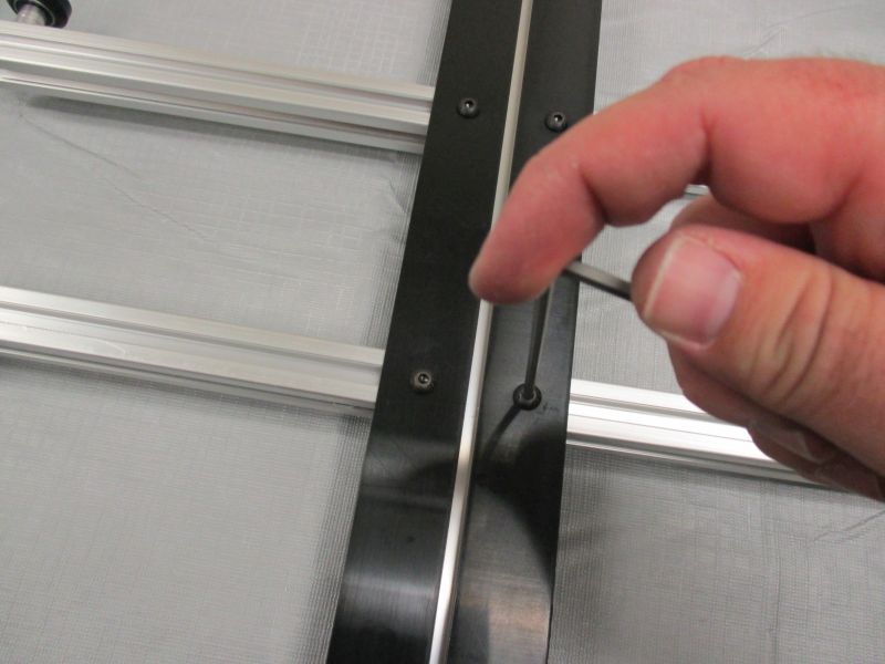
Turn assembly over and snug base cover screws.
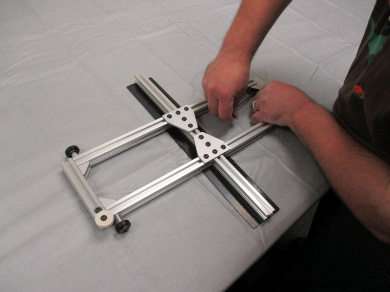
Slide (4) Corner Brackets onto inside slots of the Base Struts.
With the Corner Brackets loose, slide a Base Side Beam onto the two corner brackets.
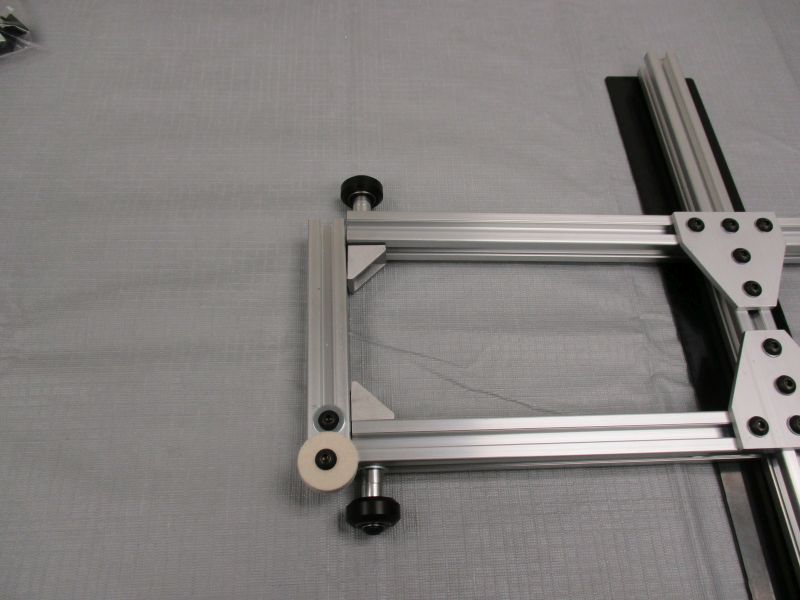
Snug corner bracket screws with Base Side Beam aligned against the ends of (2) Base Struts.
Repeat on other side.
 Some corners may not be square. You can adjust the orientation of the beams by loosening a few screws at a time, adjusting orientation, and re-tightening.
Once the corners are close to square, tighten up all of the screws including the V-Wheel screws. Final adjustment is done later during assembly of the main structure.
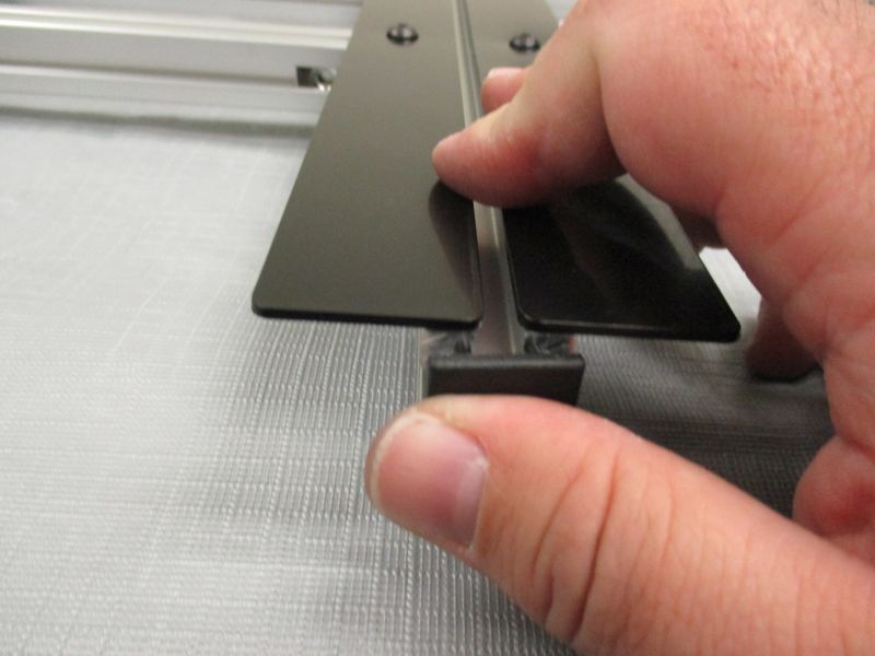
Gather (2) Plastic End Caps. Press a Plastic End Cap into each end of the Base Center Beam.
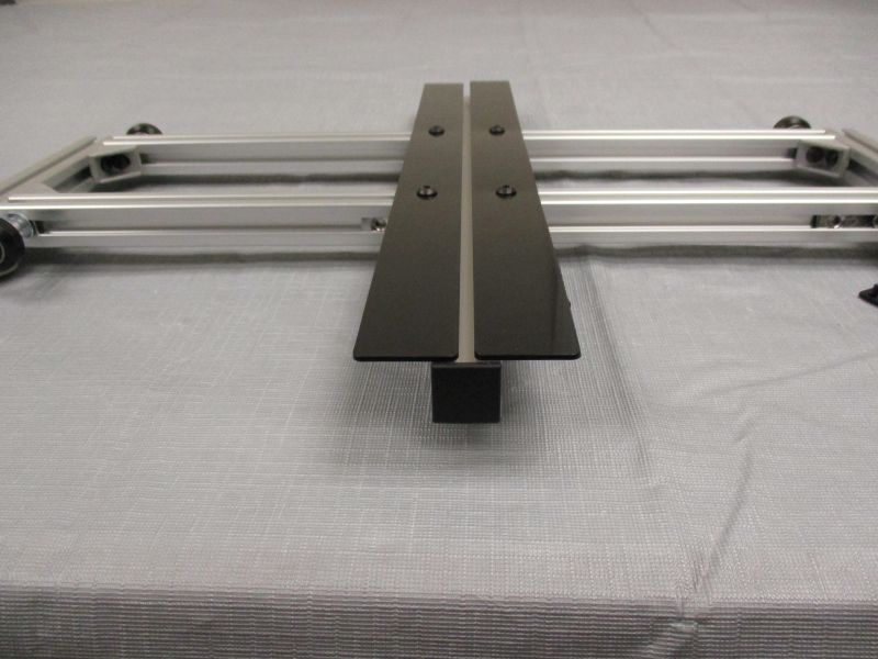
The Cradle Base is now complete. Set it aside for use during Main Structure Assembly