Cradle Lifter Assembly
Special Notes
M5 Washers and 1.00mm Spacers look very similar. Do not mix them up.
Inventory
Tools Needed:
- 3mm Hex Key
- Wrench
Parts Needed:
- (1) Cradle Lifter Assembly Bag
- (2) Lifter Rail
- (2) Lifter Plate
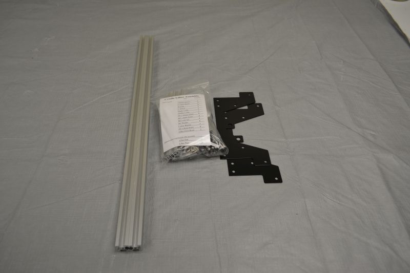
Gather parts together and remove plastic coating from extrusion pieces if necessary. Use the part list in the Cradle Lifter Assembly Bag to verify that all parts are present before beginning. Notify help@tenrec.builders if any parts are missing.
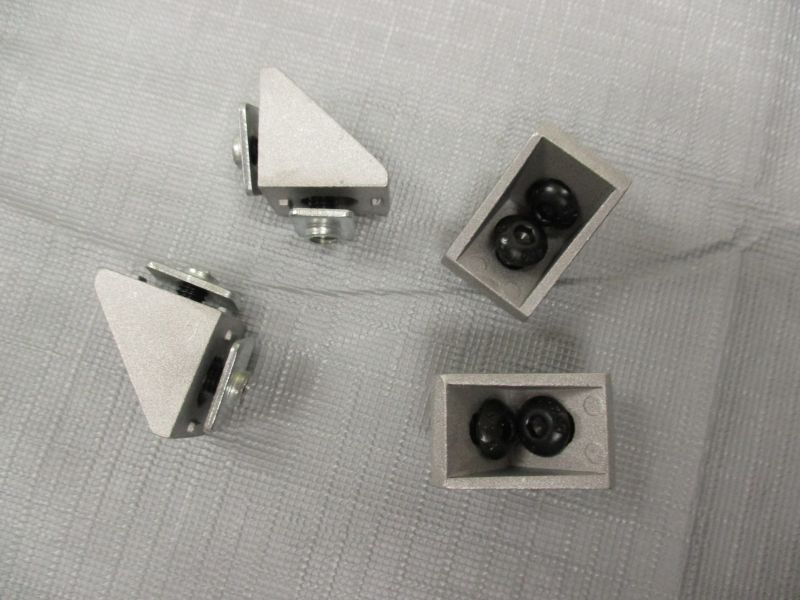
Preload (4) Corner Brackets
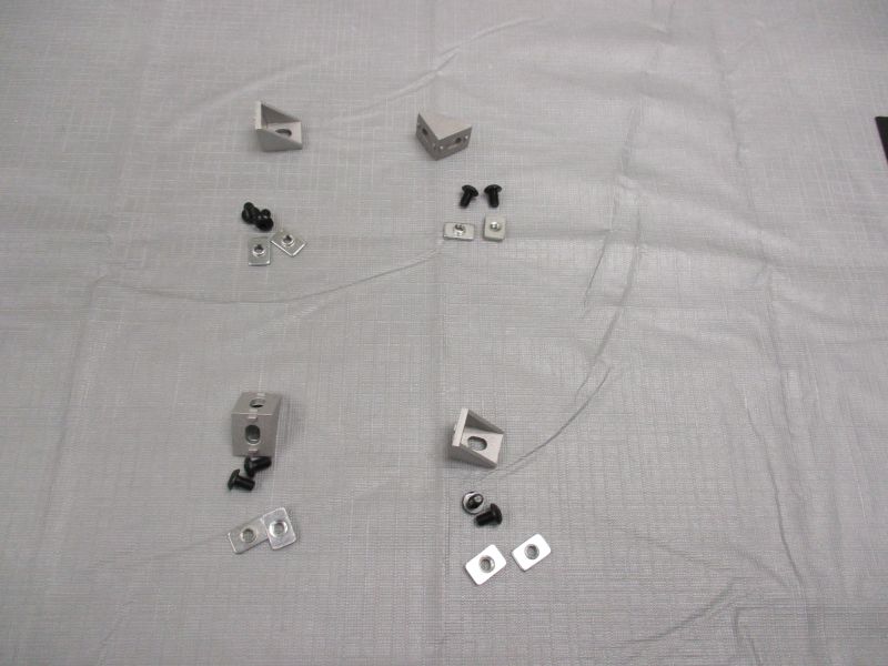
Each Corner Bracket uses (2) M5 x 8mm Screws and (2) Single T-Nuts.
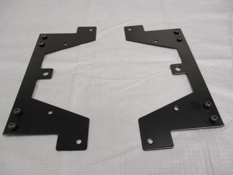
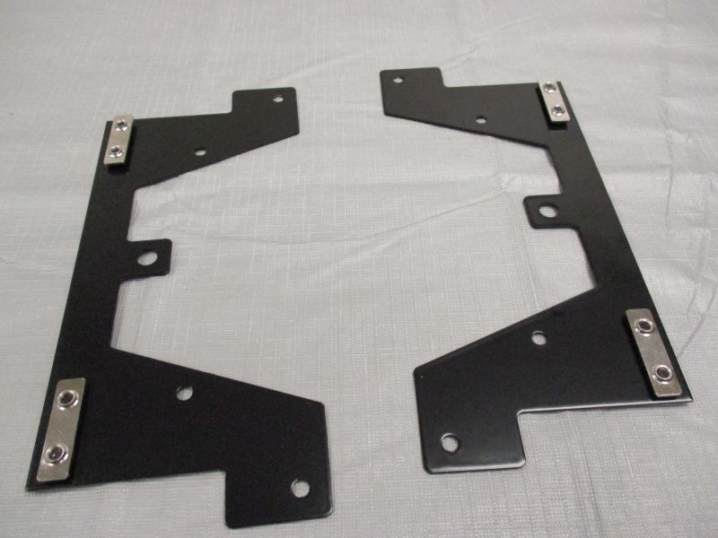
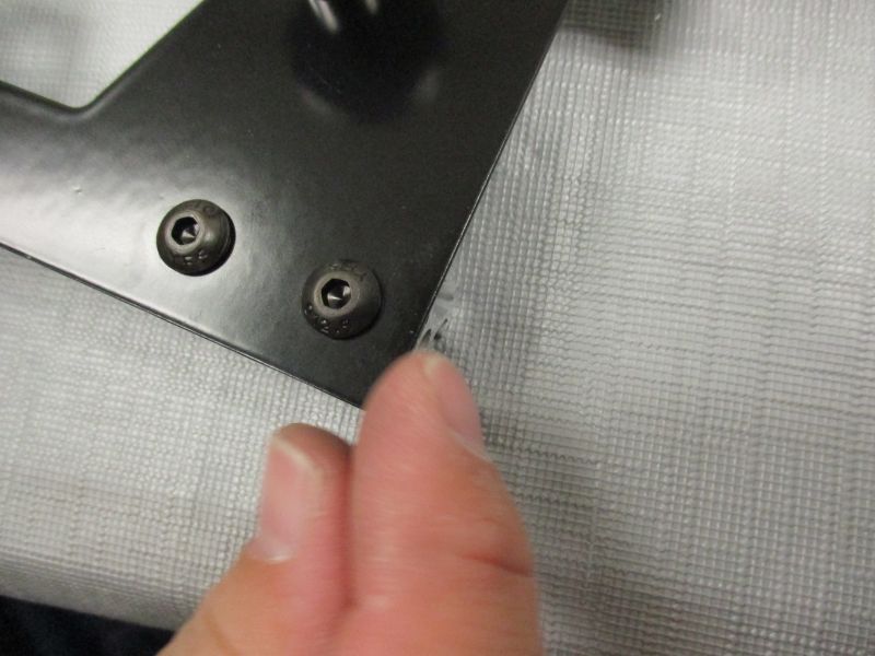
Preload (2) Lifter Plates
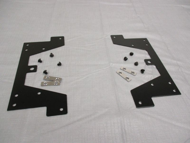
Each Lifter Plate uses (4) M5 x 6mm Screws and (2) Double T-Nuts.
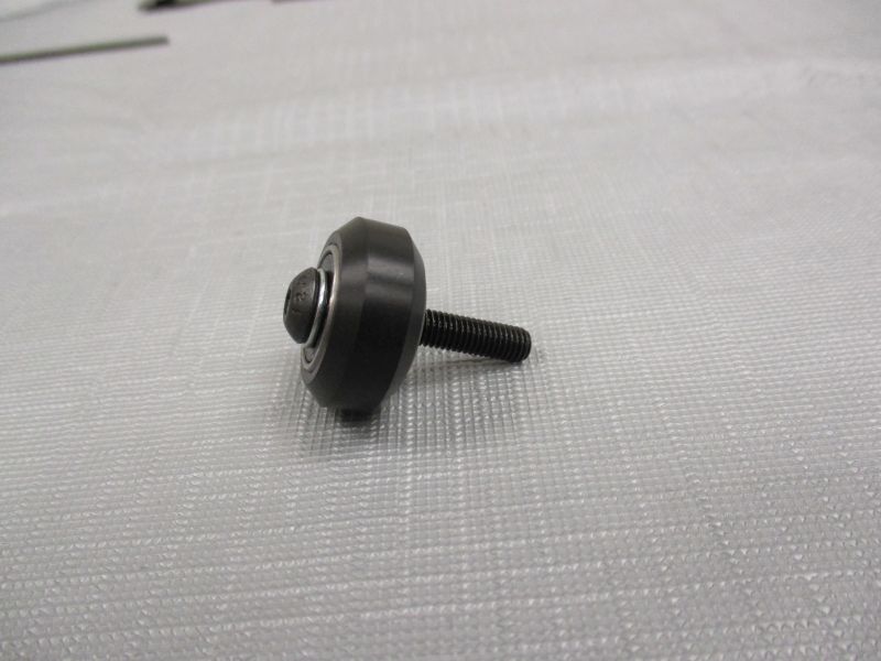
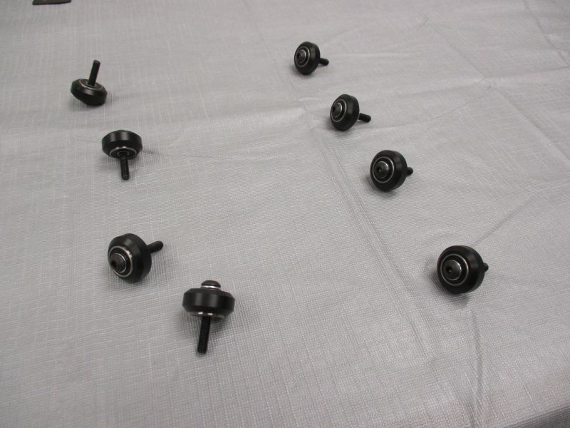
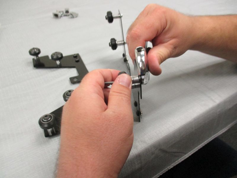
Assemble (8) V-Wheels
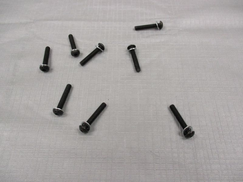
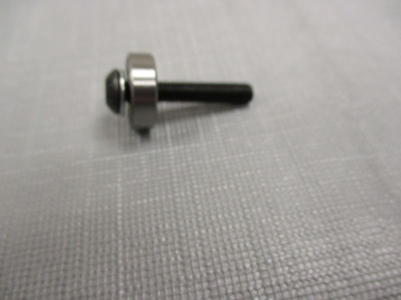
Take (8) M5 x 30mm Screws and put an M5 Washer on each one. This will help avoid mixups in the following steps.
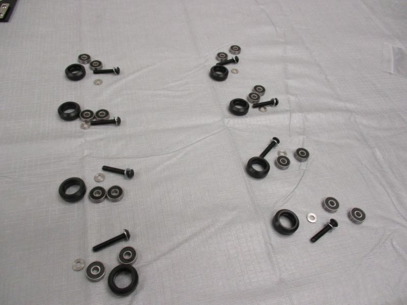
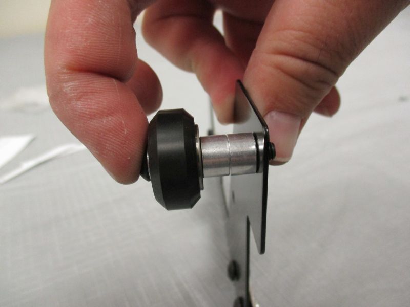
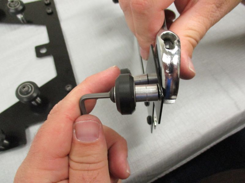
Each V-Wheel uses (1) M5 x 30mm Screw with attached M5 Washer, (1) 1.00mm Spacer, and (2) Bearings.
Place (1) Bearing on each M5 x 30mm Screw.
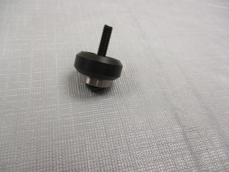
Place V-Wheel on each M5 x 30mm Screw.
Place 1.00mm Spacer on each M5 x 30mm Screw.
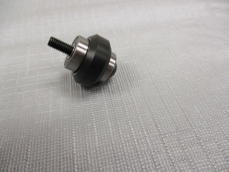
Place (1) Bearing on each M5 x 30mm Screw.
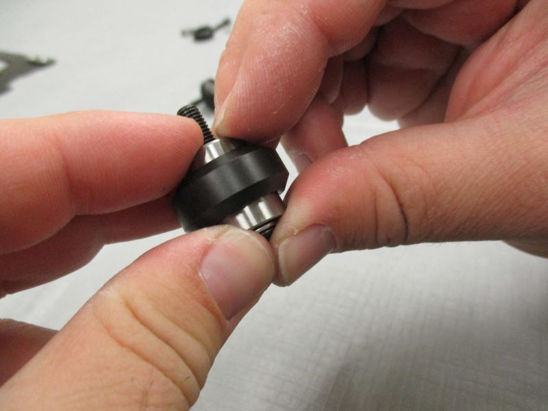
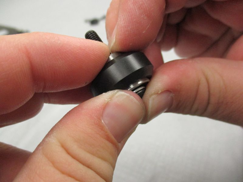
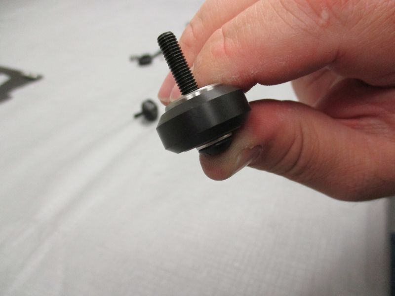
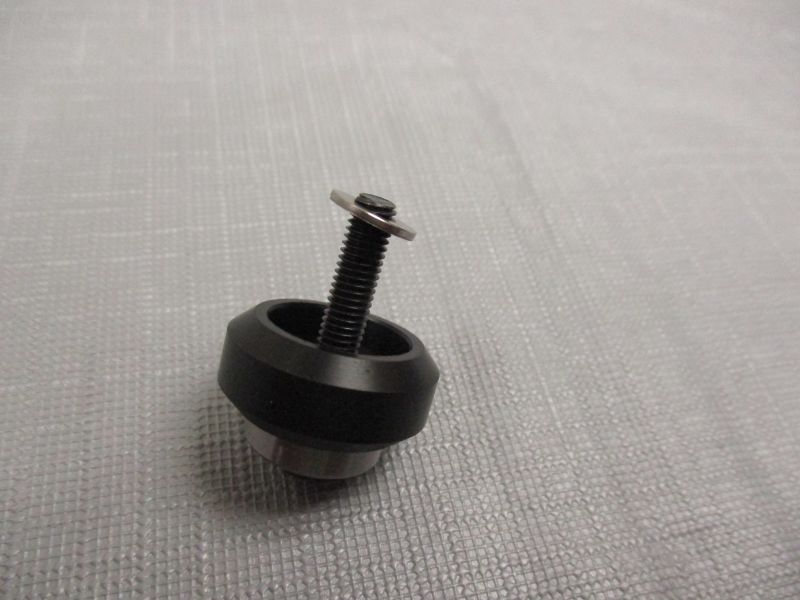
Press assembly together with fingers. If you have trouble, temporarily thread a spare Double T-Nut on the M5 x 30mm Screw and tighten to press the assembly together.
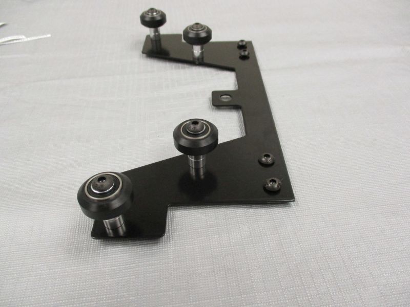
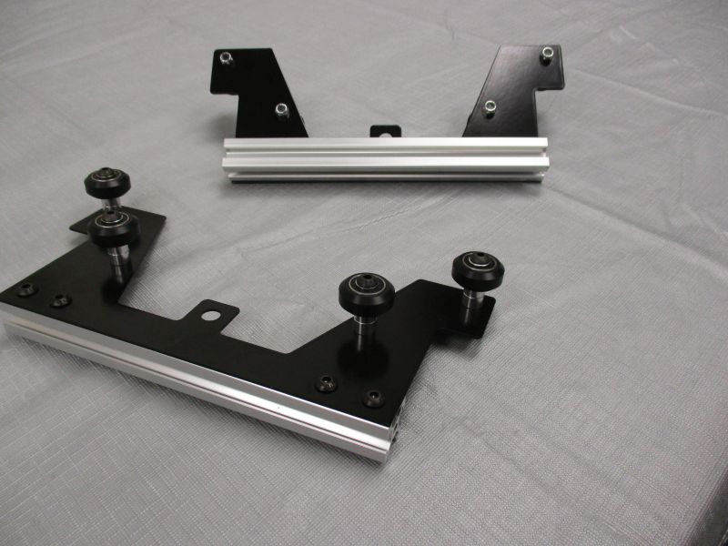
Attach (8) V-Wheel Assemblies
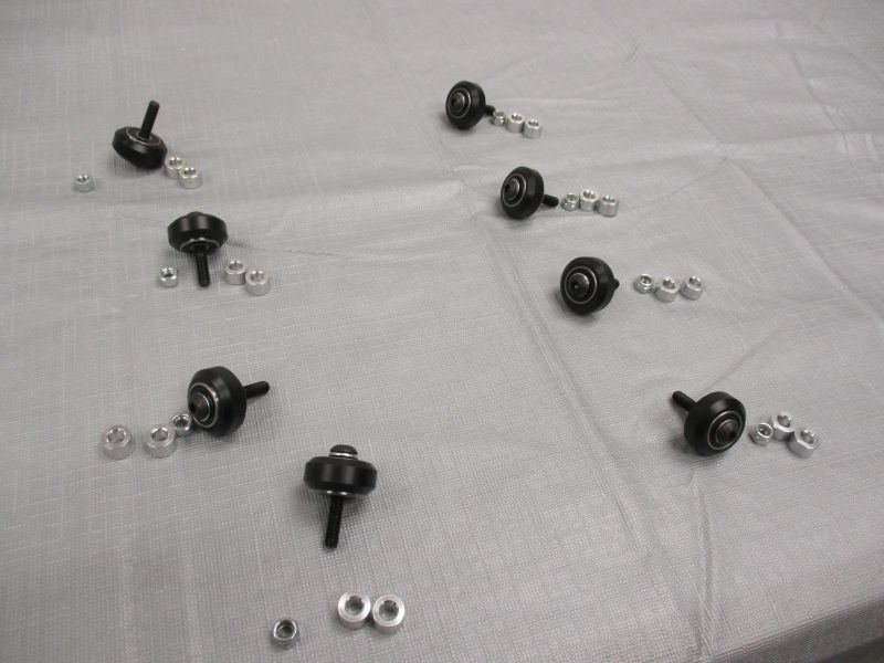
Each V-Wheel Assembly uses (1) M5 Lock Nut and (2) 6.35mm Spacers.
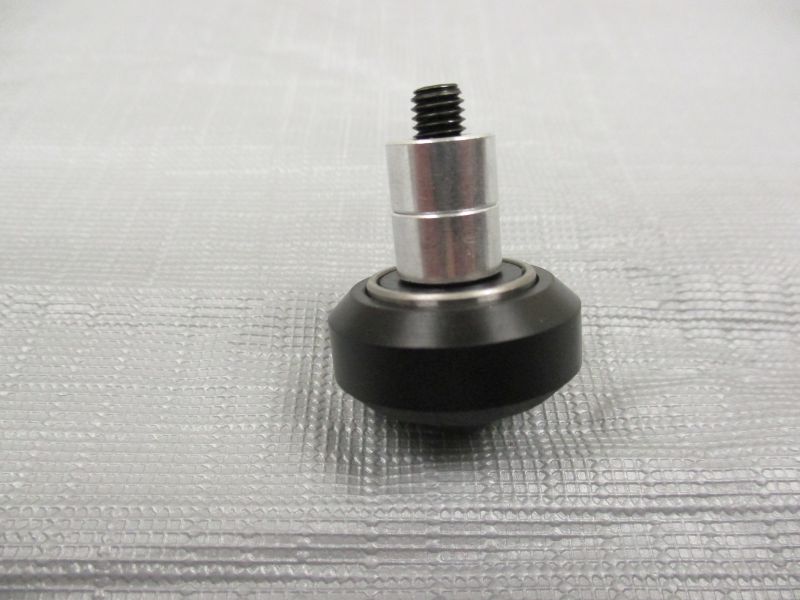
Place (2) 6.35mm Spacers on each V-Wheel Assembly.
Place Wheel Assembly in one of the holes in the Lifter Plate.
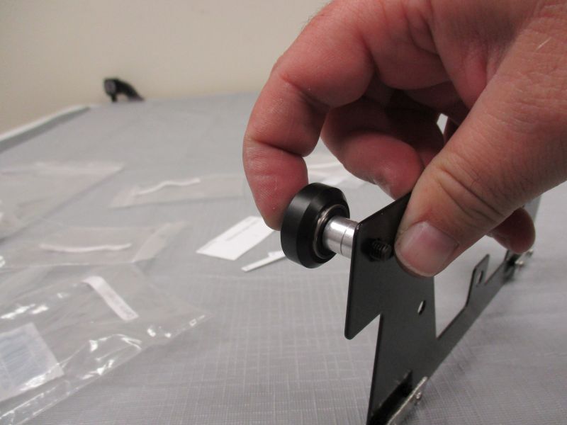
The V-Wheel should lie on the opposite side of the plate from the Double T-Nuts.
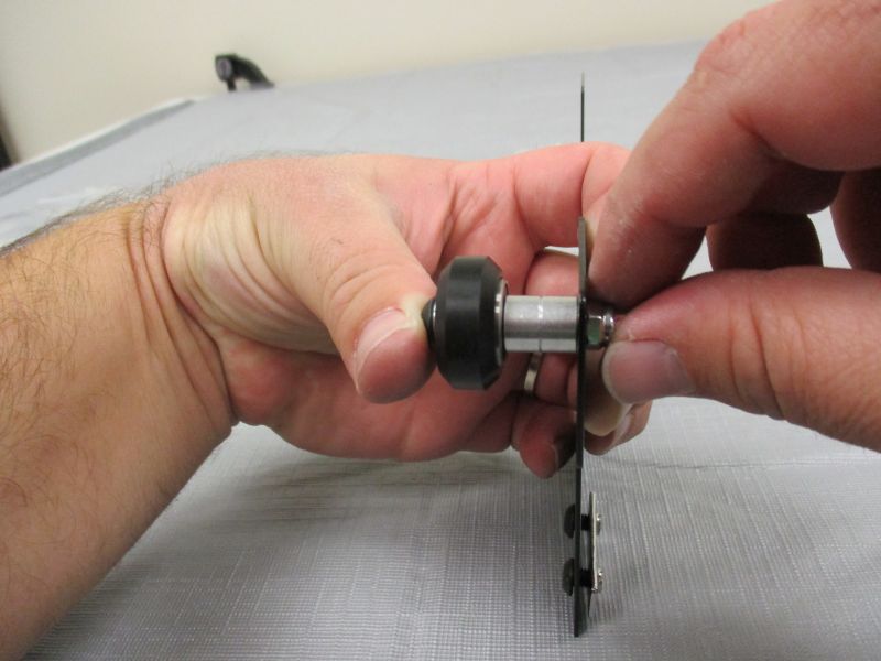
Finger-tighten an M5 Lock Nut onto the V-Wheel Assembly.
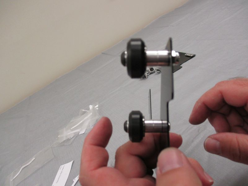
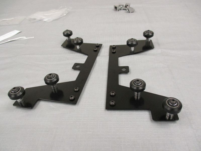
Repeat with the remaining V-Wheel Assemblies.
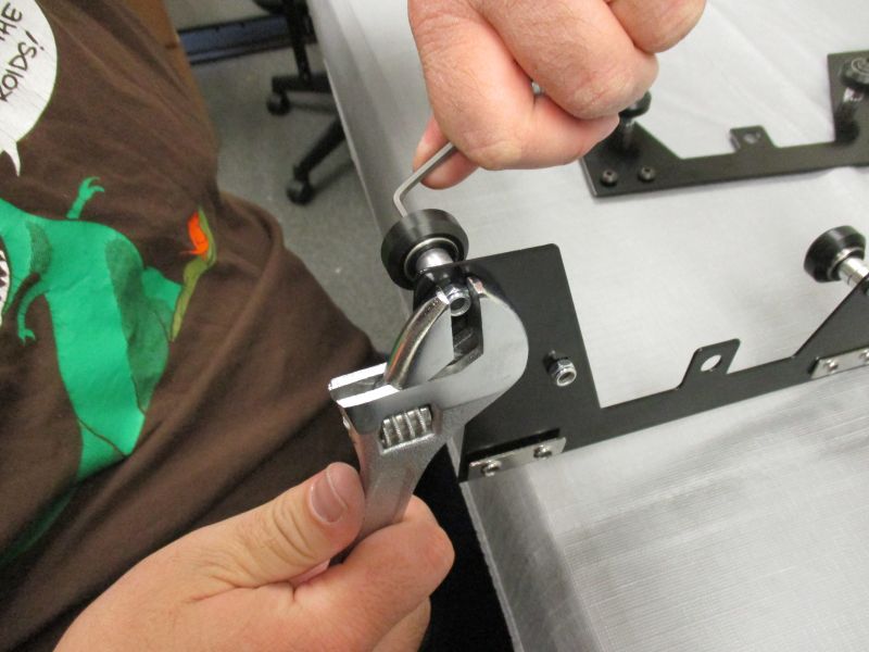
Tighten V-Wheel Assemblies using a 3mm Hex Key and Wrench.
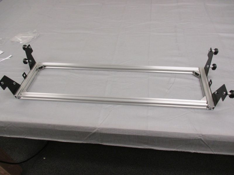
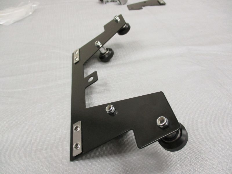
Assemble Lifter
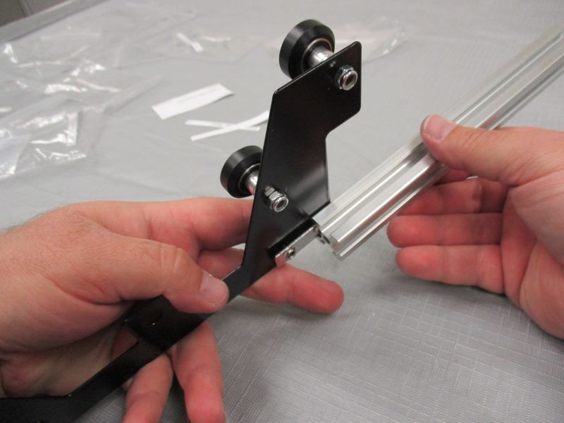
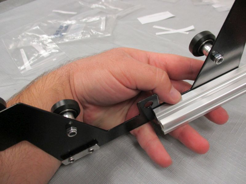
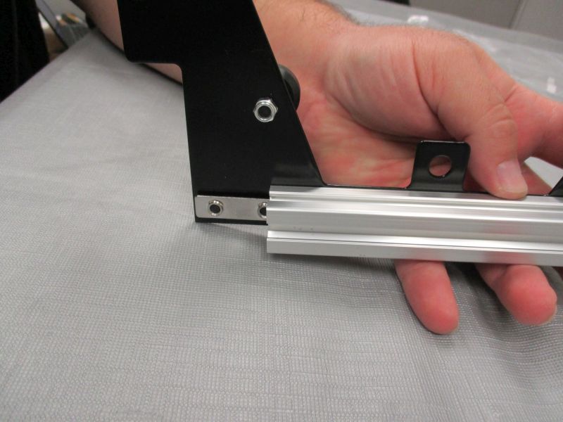
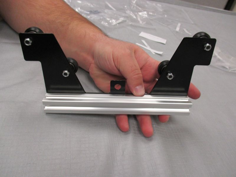
Slide Lifter Plate onto Lifter Side Beam.
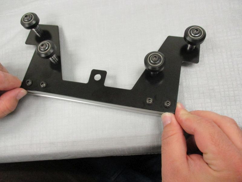
The Lifter Plate should be flush with the bottom and ends of the Lifter Side Beam. Align the Lifter Plate and then tighten the screws.
Repeat with the remaining Lifter Plate and Lifter Side Beam.
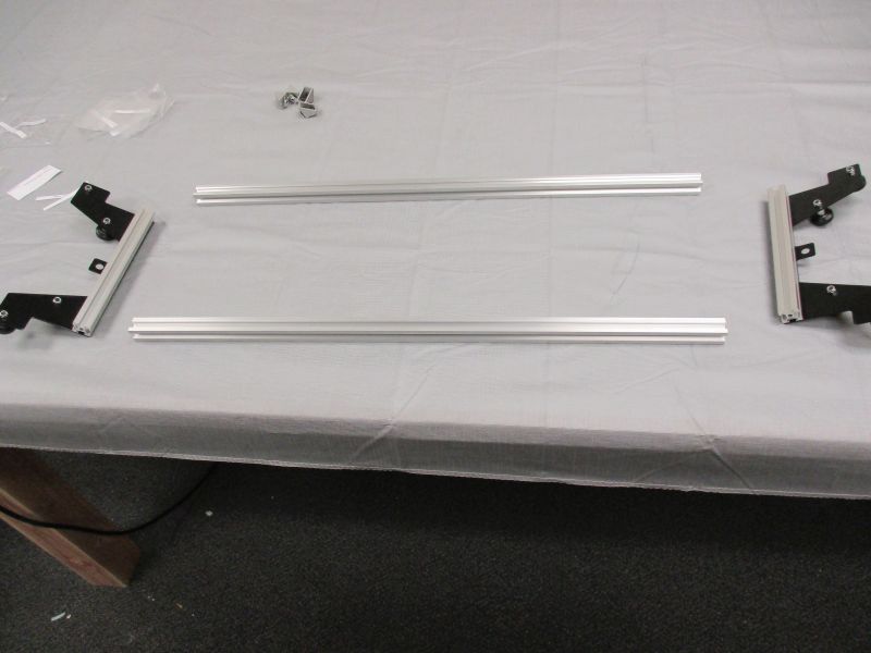
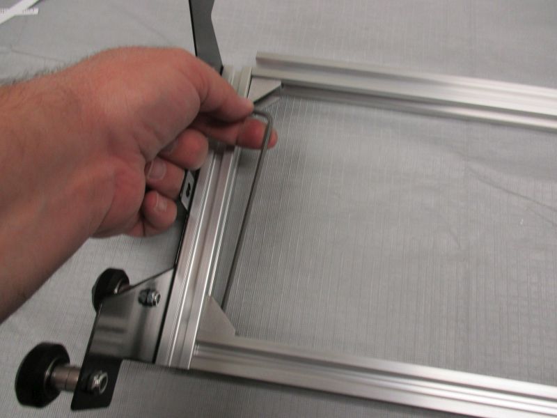
Arrange Lifter Rails, and Lifter Side Beam Assemblies into a rectangle. Gather (4) Corner Bracket Assemblies.
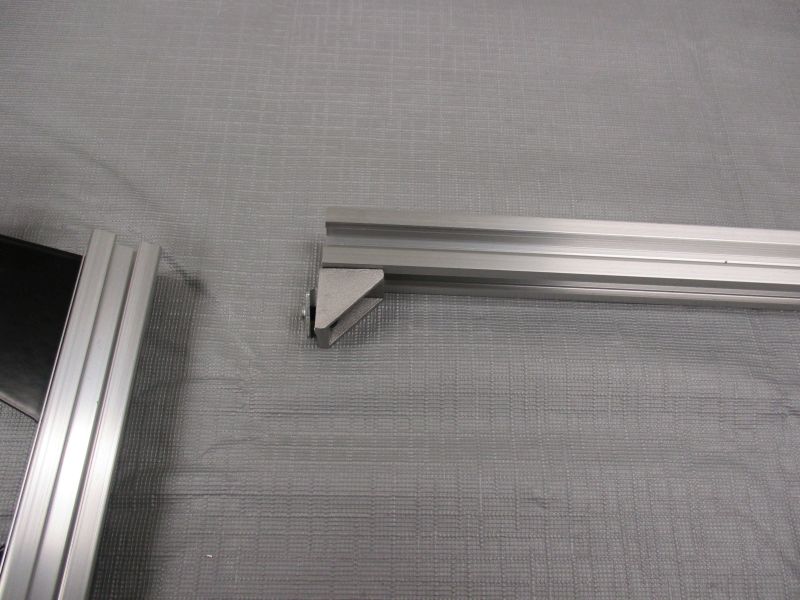
Slide Corner Bracket Assembly onto Lifter Rail.
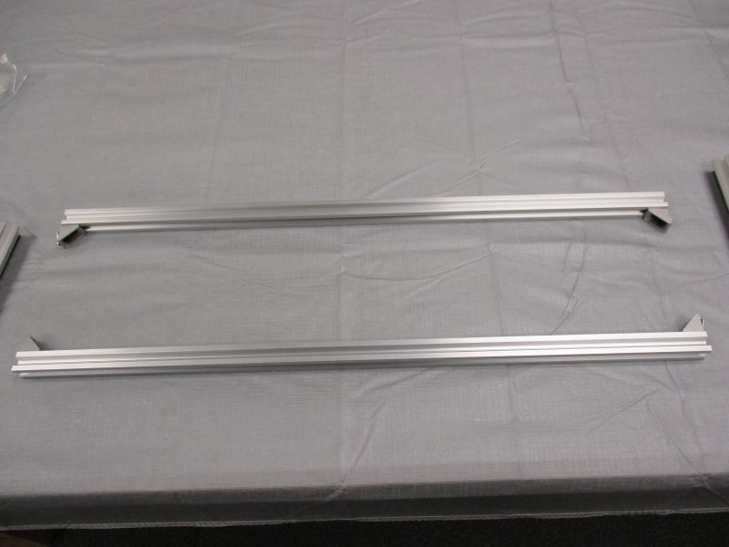
Repeat at other corners.
Slide Lifter Side Beam Assemblies onto the corner brackets at each side. Snug screws.
Loosen and adjust alignment of beams and corner brackets until assembly is squared. Tighten all screws.