Completing the Main Structure
Special Notes
In addition to the parts listed below, you will need to temporarily borrow a few pieces from the Handlebar Assembly to assist with final positioning of the pieces.
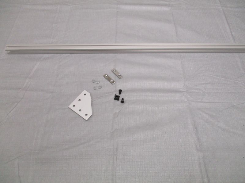
You will use an L-Plate, 2 Double T-Nuts, 4 M5 x 10mm Screws, 4 M5 Washers, and a Long Beam during final positioning. Once complete, they are used as components of the Handlebar Assembly.
Inventory
Tools needed:
- 3mm Hex Key (in Tool Bag)
Parts needed:
- Platform Assembly
- Cradle Lifter
- Cradle Base
- Cradle Wings
- Imaging Module
- Platen Module
- (2) Glass Plates
Attach Cradle Lifter
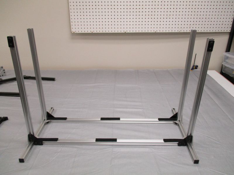
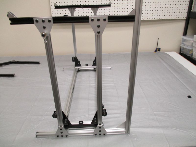
Gather the Platform Assembly. Loosen the screws holding the vertical rails.
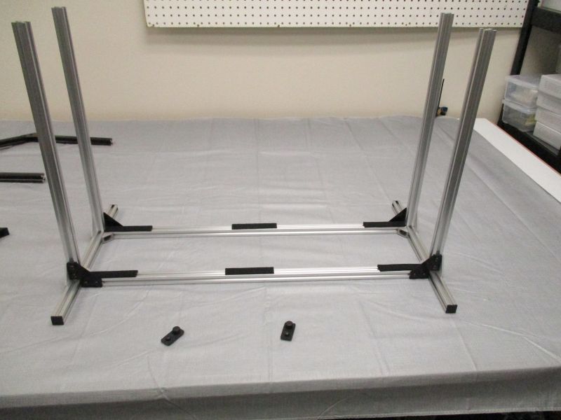
Remove Cradle Stops from Platform Assembly and set them aside.
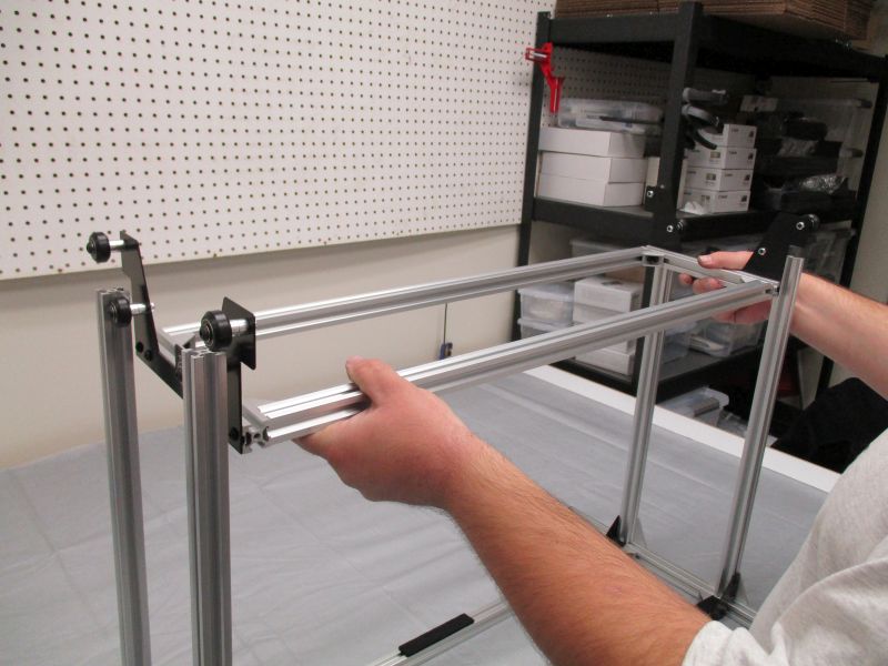
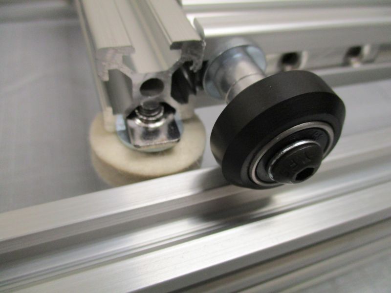
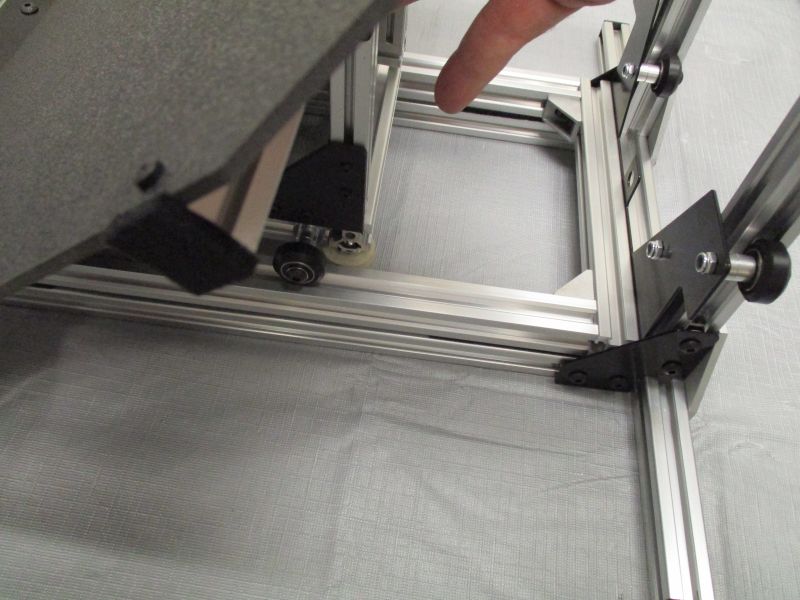
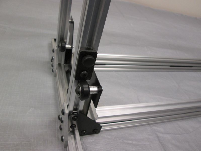
Lower Cradle Lifter onto Vertical Rails.

Guide wheels into the V-Slots on each side. Be careful of the sharp corners of the Vertical Rail extrusion.

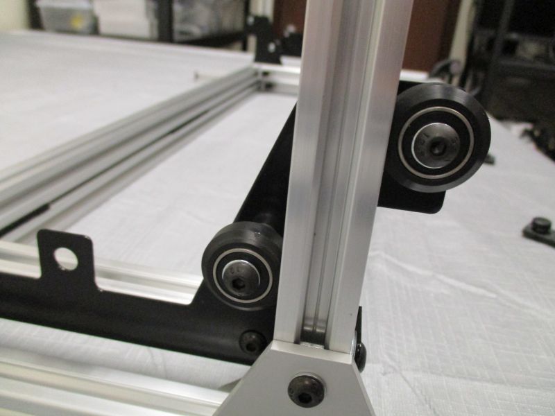
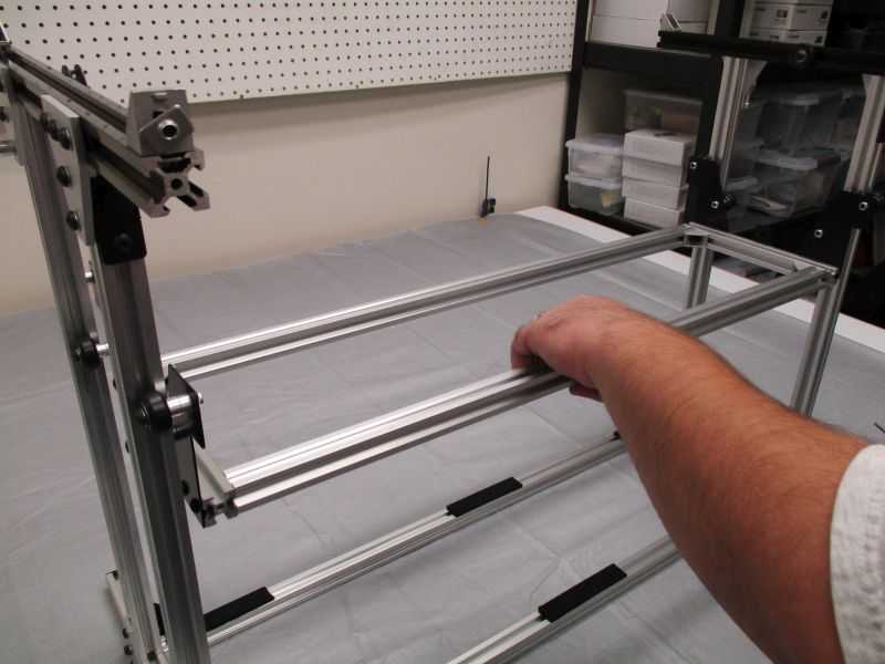
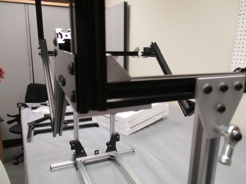
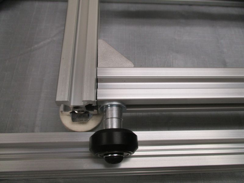
Once all wheels are on the rails, lower the Cradle Lifter down so that the it rests on the Long Beams of the Platform Assembly.
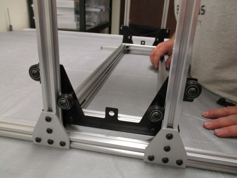
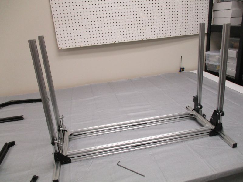
The Cradle Lifter Rails should lie directly on top of and flush with the Long Base Beams. The Vertical Rails should look vertical. If this is not the case, remove the Cradle Lifter and adjust the Platform Assembly more precisely using the Platform Guide.
Add Platen Assembly Sides
Put Cradle Stops back on the two front Vertical Rails. Snug screws holding the Vertical Rails. The front of the scanner is the side with the two Cradle Stops.
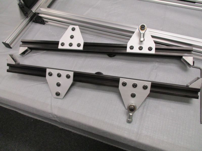
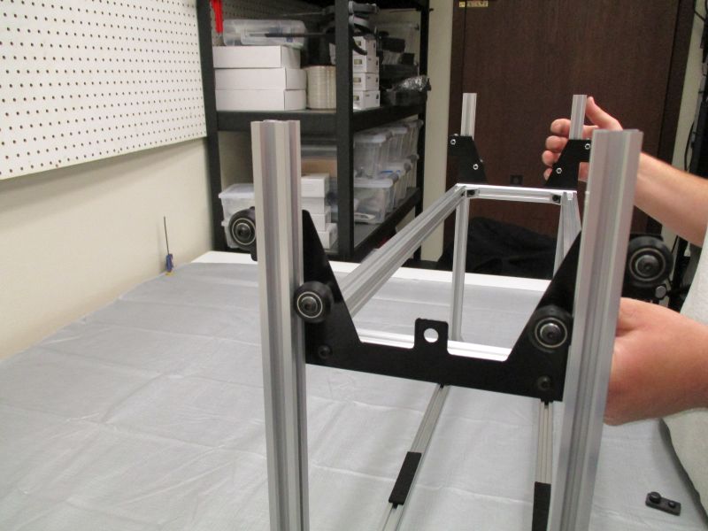
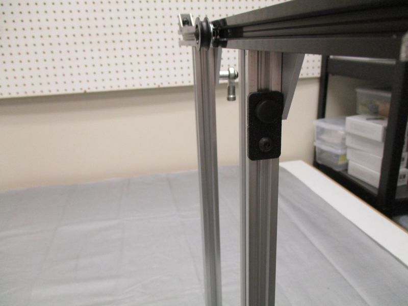
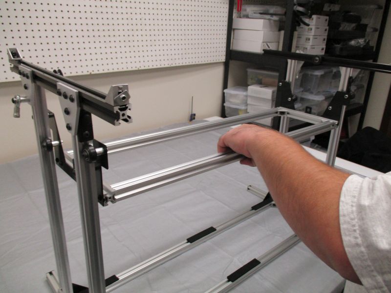
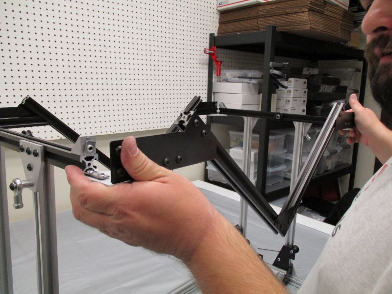
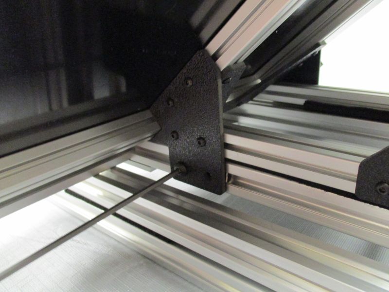
Gather 2 Black Cross Beam Sides from Platen Assembly. Loosen the screws of the T-Plates.
Slide a Black Cross Beam Side onto a pair of Vertical Rails. The T-Plate with Rod End will be towards the back of the Scanner (opposite the Cradle Stops).
Repeat with the other Black Cross Beam Side.
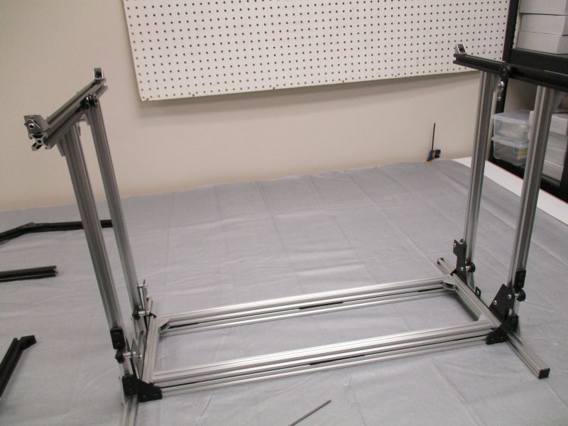
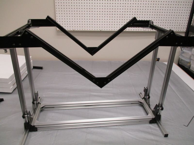
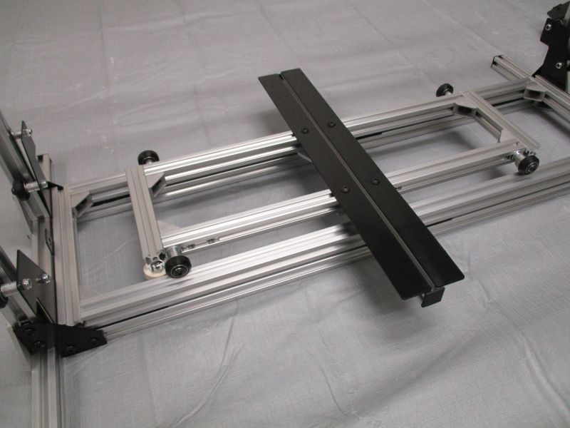
Align Black Cross Beam Sides
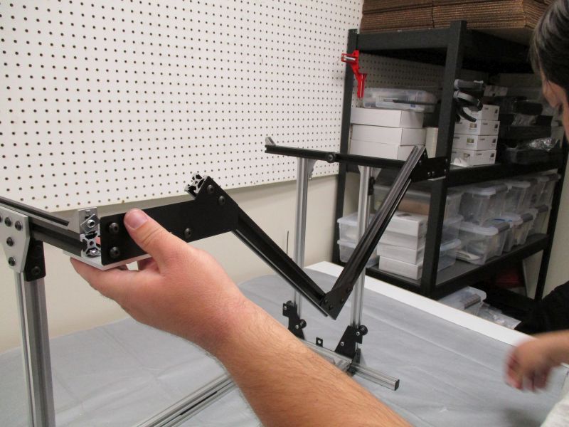
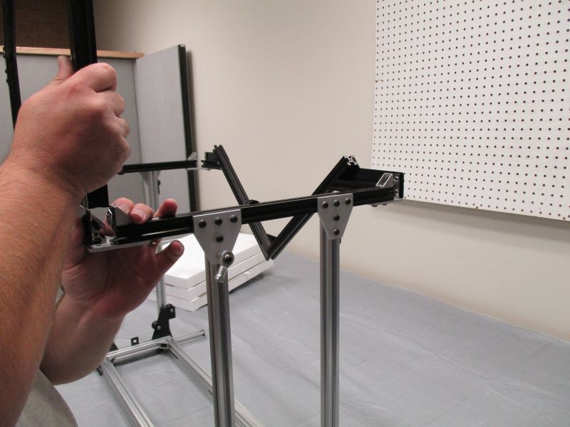
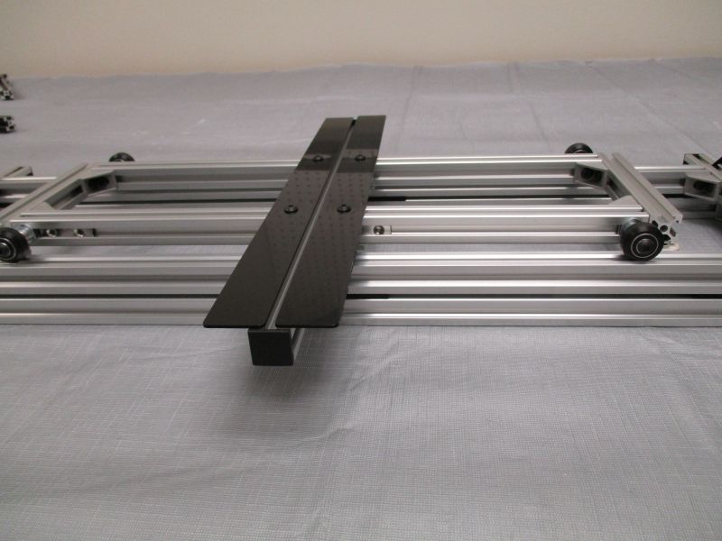
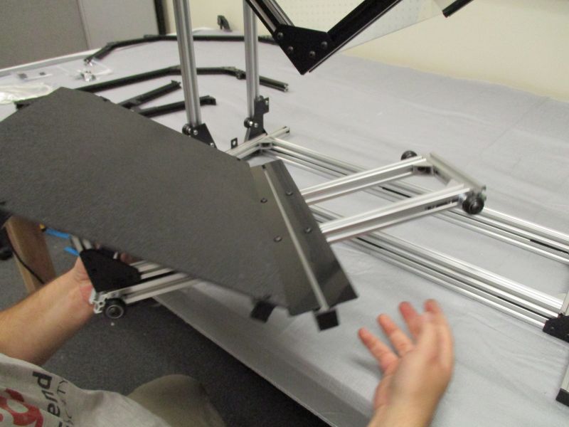
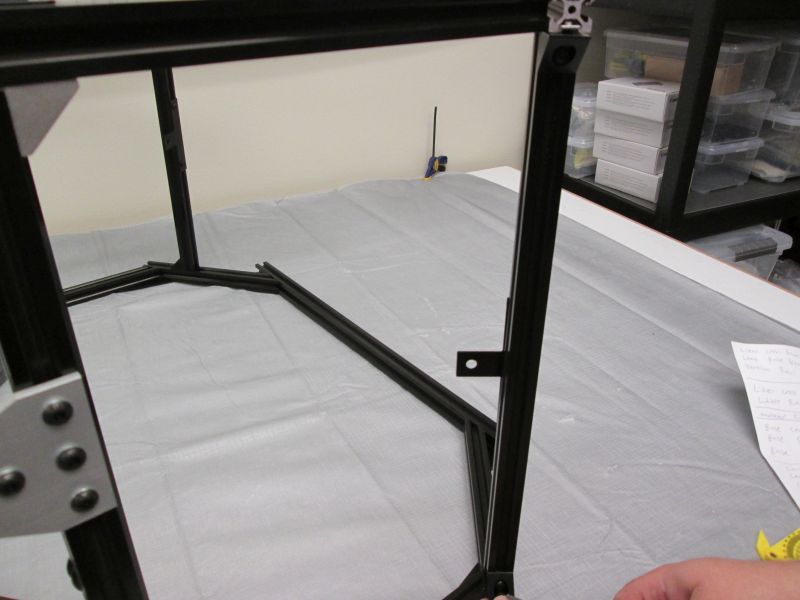
Make a temporary alignment jig from pieces of the Handlebar Assembly. Once alignment is complete, we will disassemble the jig and return them to their bags.
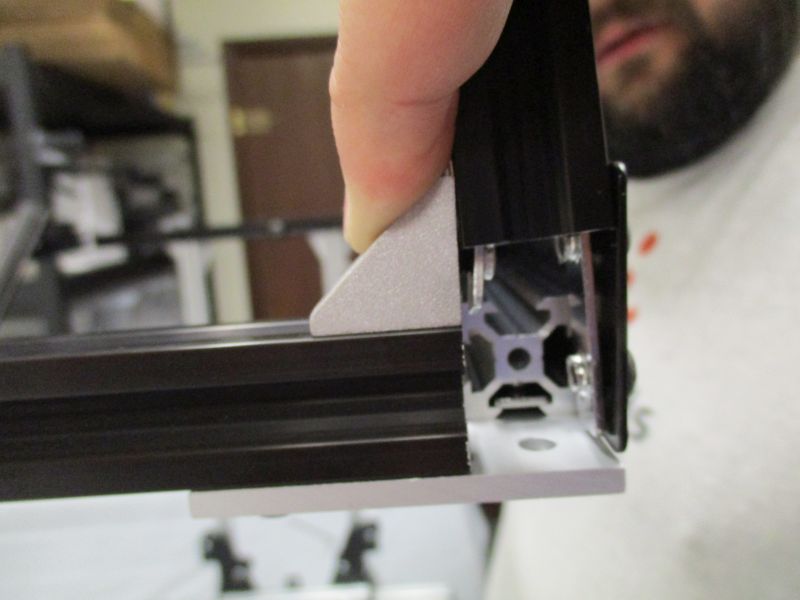
Remove the two Plastic End Caps from the front of the two Clear Cross Beams in the Platform Assembly. Set them aside.
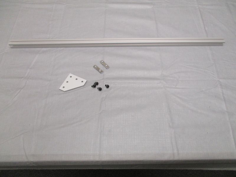
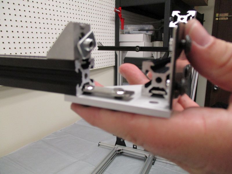
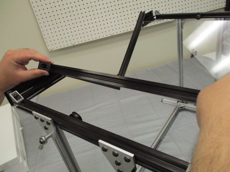
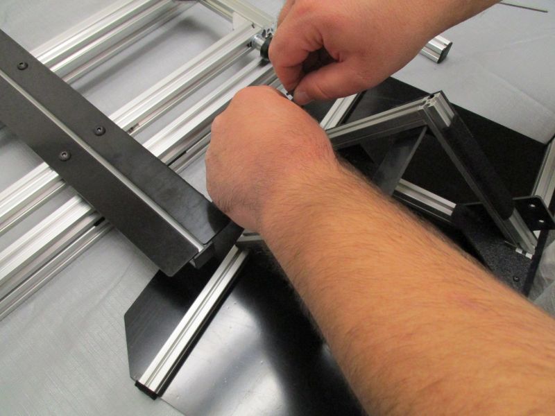
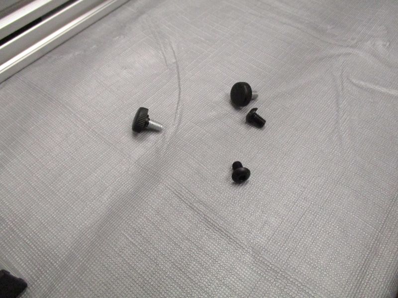
From the Handlebar Assembly, gather (1) Long Beam, (1) L-Plate, (4) M5 x 10mm Screws, (4) M5 Washers, and (2) Double T-Nuts.
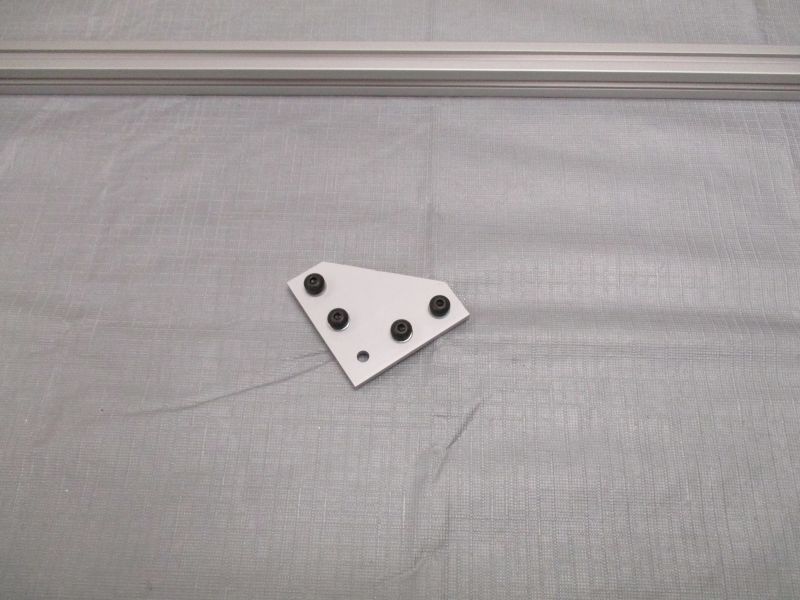
Preload the L-Plate using (4) M5 x 10mm Screws, (4) M5 Washers, and (2) Double T-Nuts.
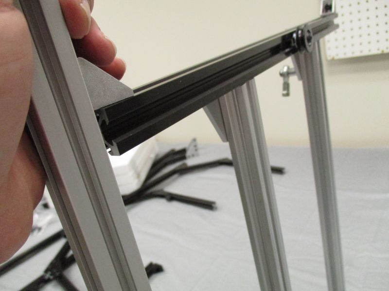
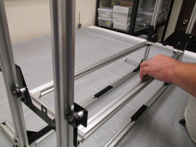
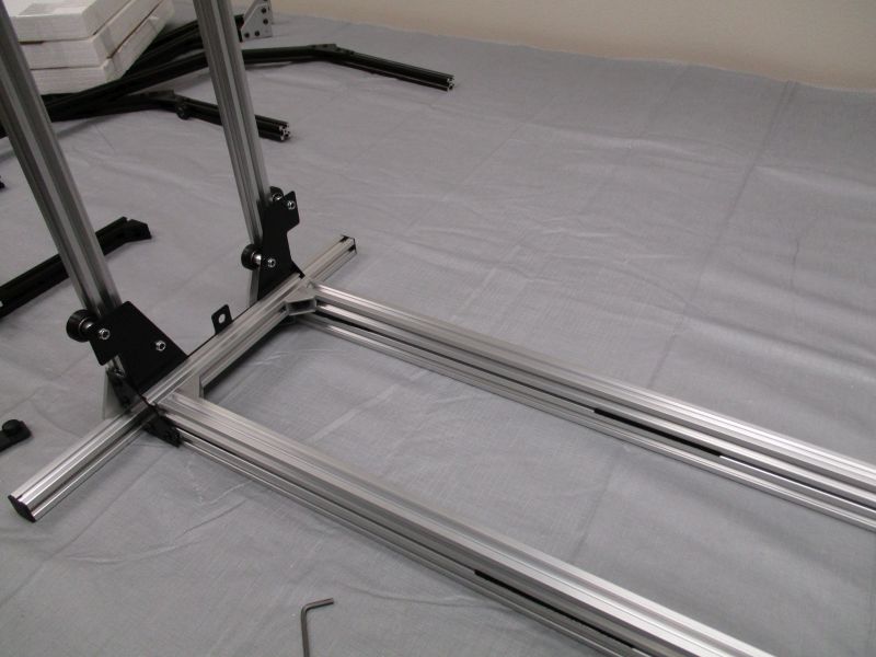
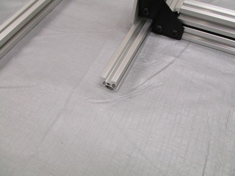
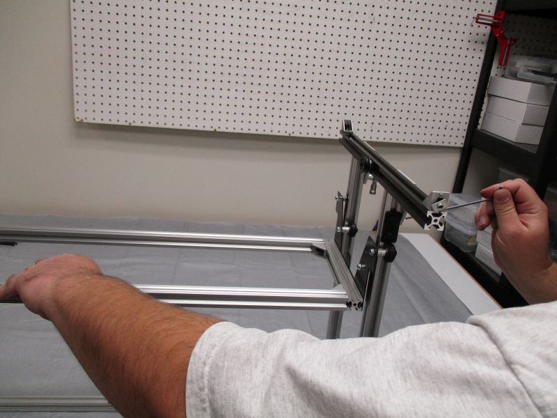
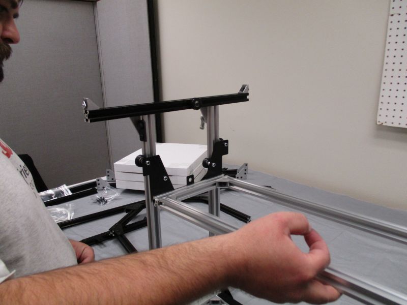
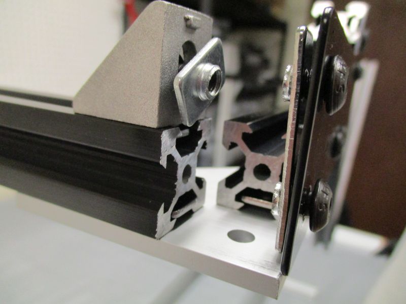
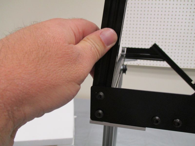
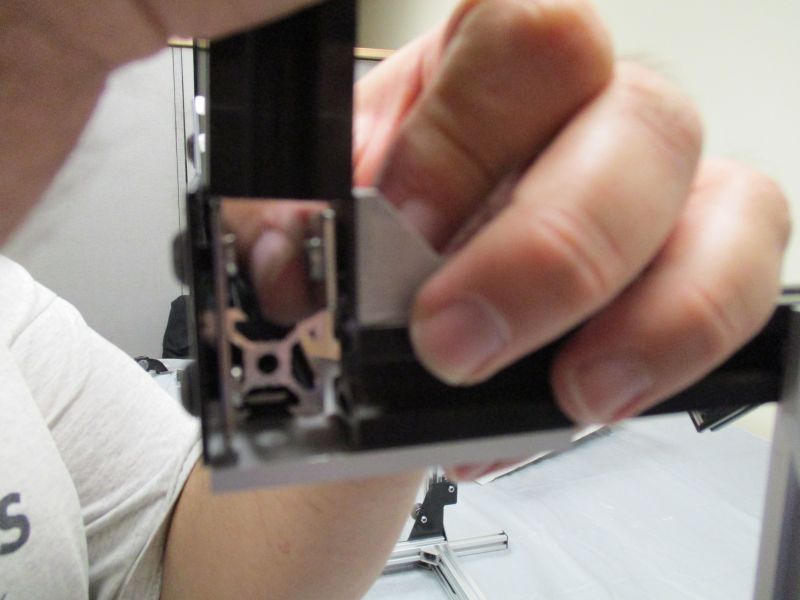
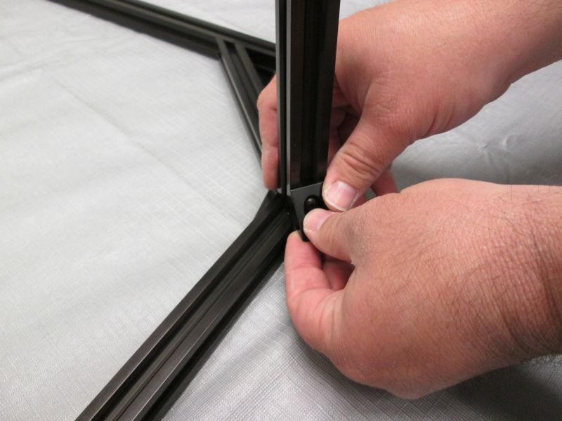
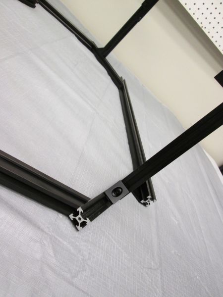
Slide Long Beam onto the corner bracket of the Black Cross Beam Side. Loosen Corner bracket as necessary.
The bottom of the Long Beam will be end up near the end of the Clear Cross Beam on the Platform Assembly.
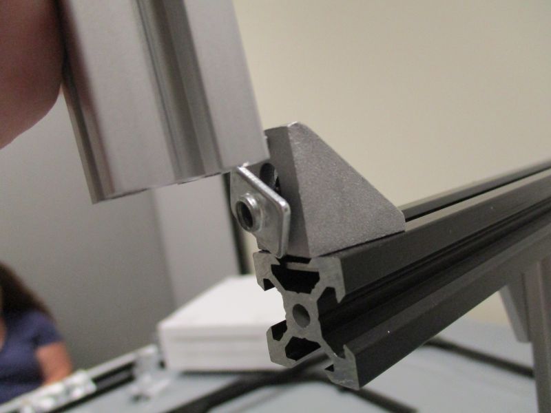
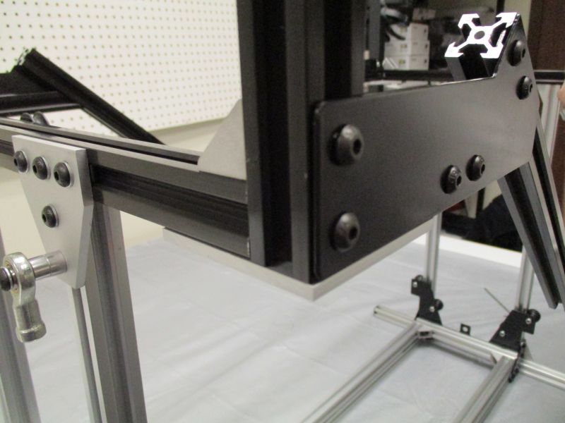
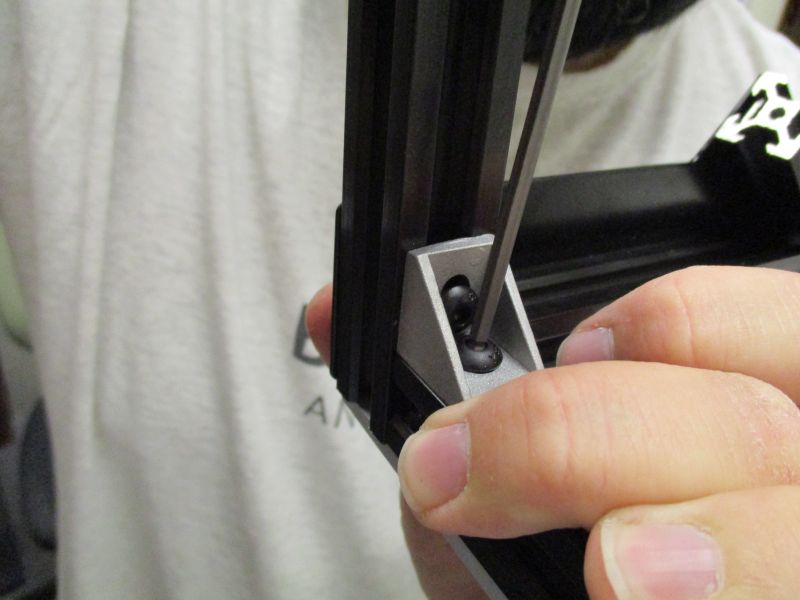
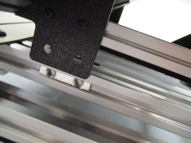
Slide the L-Plate onto the Clear Cross Beam.
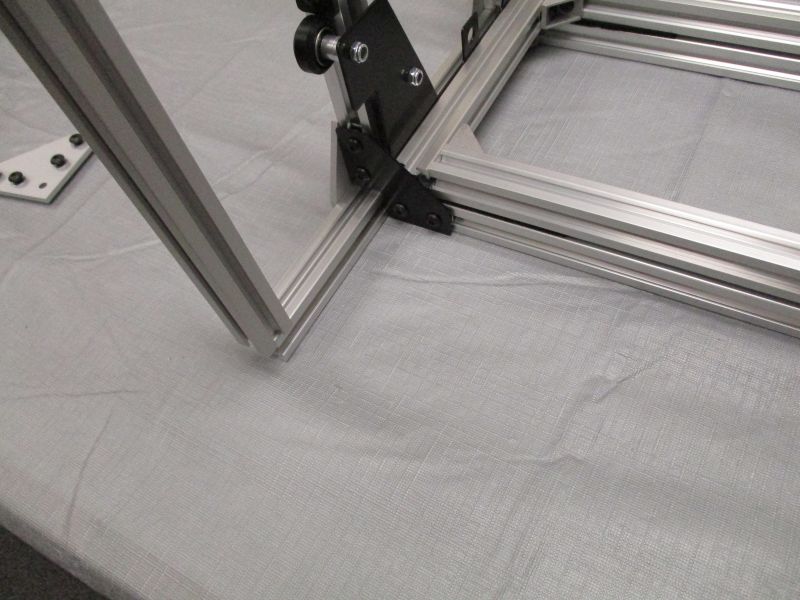
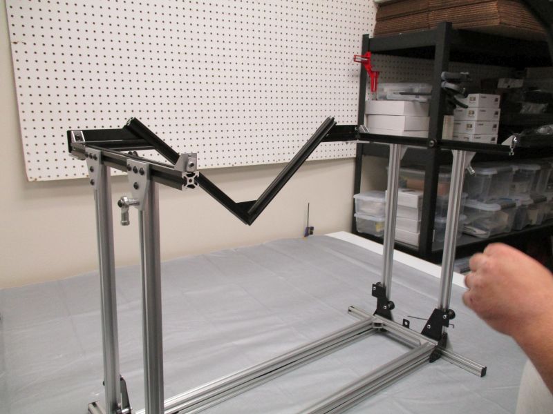
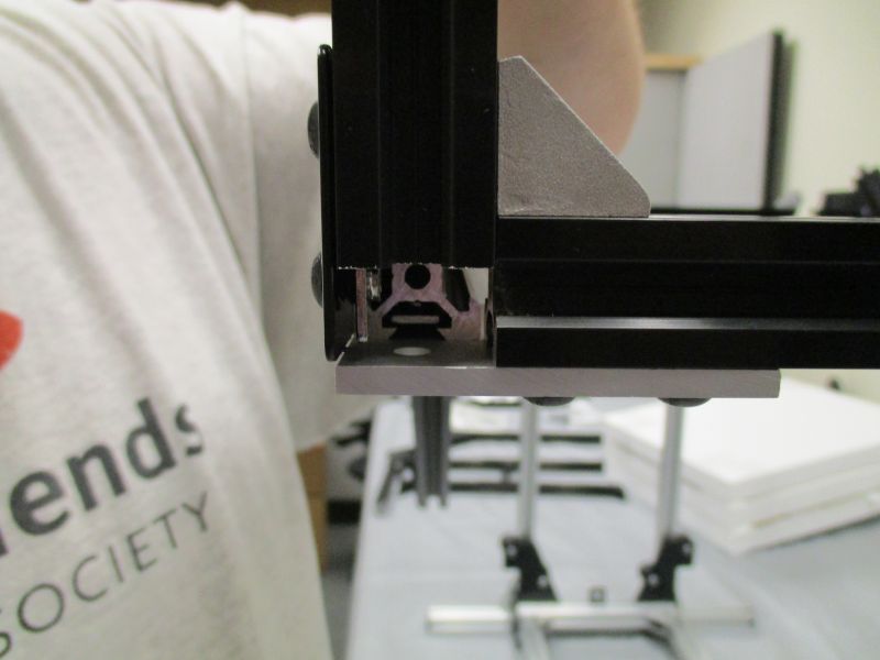
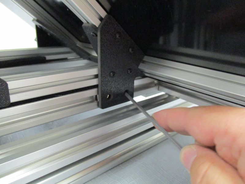
Slide Long Beam onto L-Plate. Tighten screws with the Long Beam flush with and perpendicular to the Clear Cross Beam.
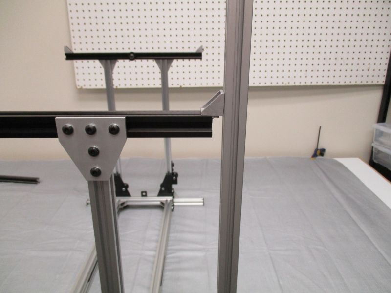
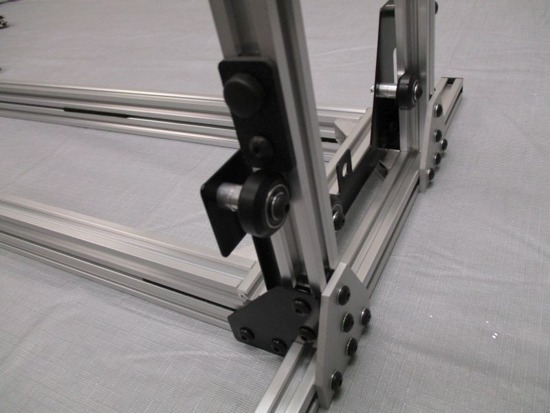
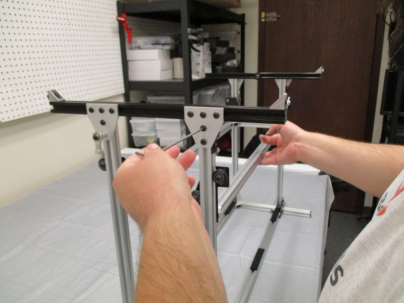
Adjust positioning of the Black Cross Beam Side as necessary. Snug Screws of Corner Bracket when aligned.
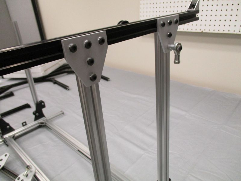
Tighten the (6) screws along the top of the top T-Plates. Tighten the (6) screws along the bottom of the bottom T-Plates. Remove Long Beam and L-Plate jig. Repeat on the other side.
Move cradle stops near the top of the Vertical Rails and tighten M5 Finger Clamp
Lift Cradle Lifter to near the top of its range. Always lift from the middle to ensure balanced movement.
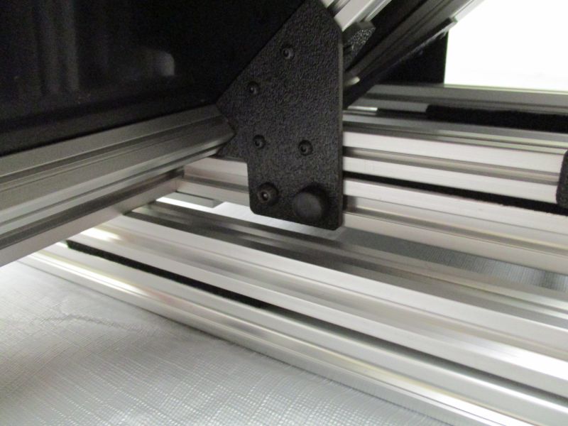
With the Cradle Lifter near the top, snug the (2) remaining screws on each top T-Plate. With the Cradle Lifter near the bottom, snug the (2) remaining screws on each bottom T-Plate. Gradually tighten them, making sure that the motion of the Cradle Lifter remains smooth and the Vertical Rails remain vertical.
Replace Plastic End Caps on Clear Cross Beams. Disassemble alignment jig and replace pieces in the Handlebar Assembly.
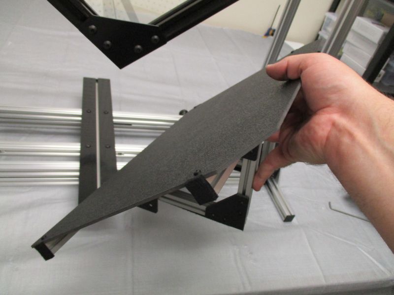
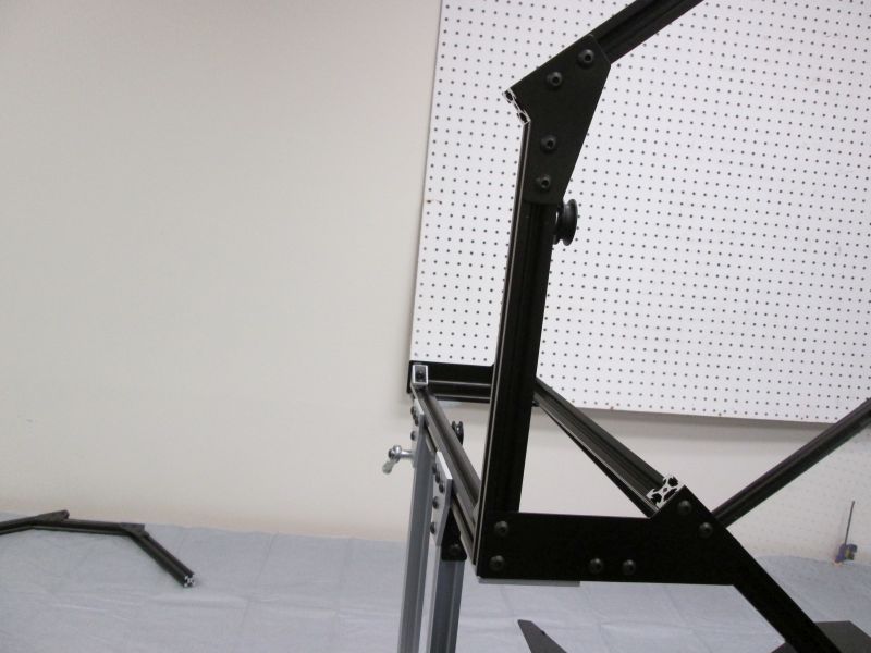
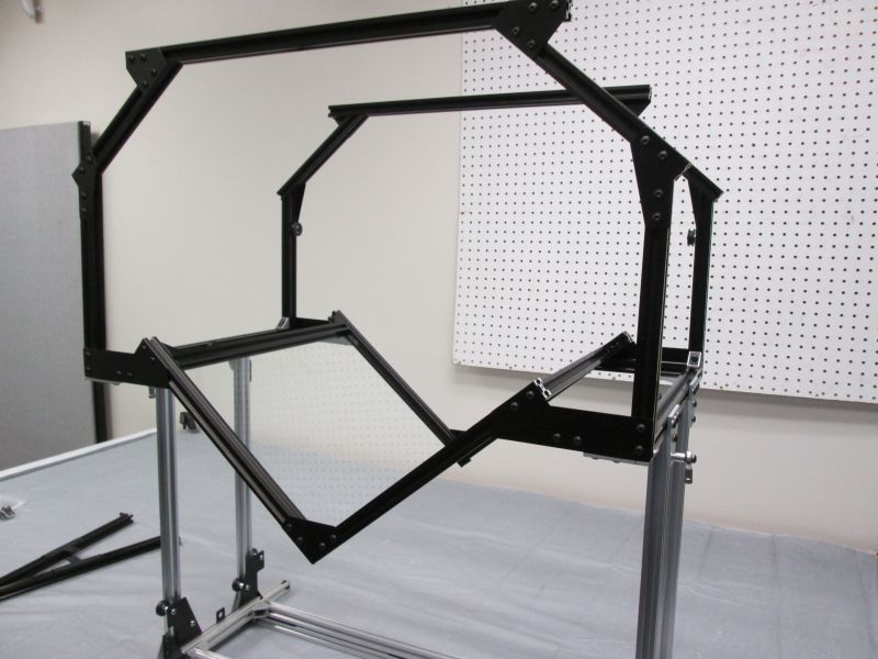
Attach Platen Front and Back
The Platen Front and Back are now attached to the sides. The Imaging Module Front and Back are used as positioning jigs in this step, but not permanently attached.
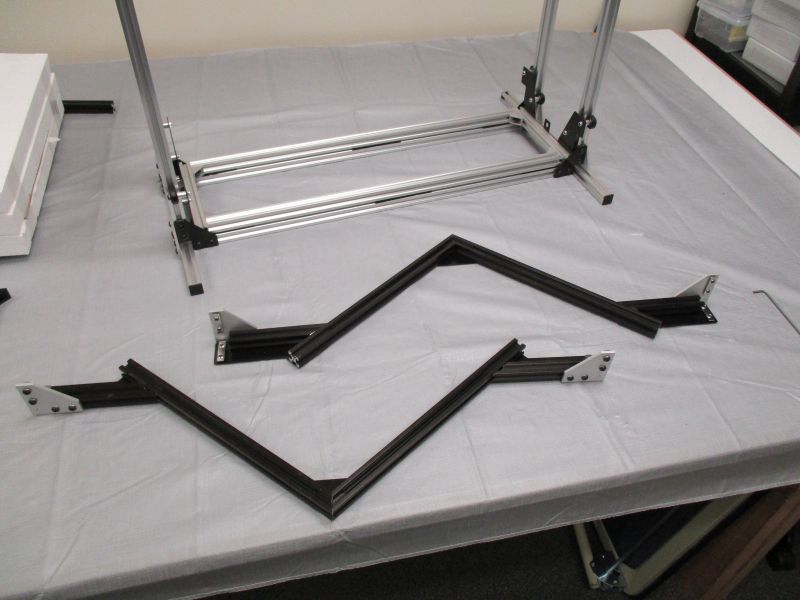
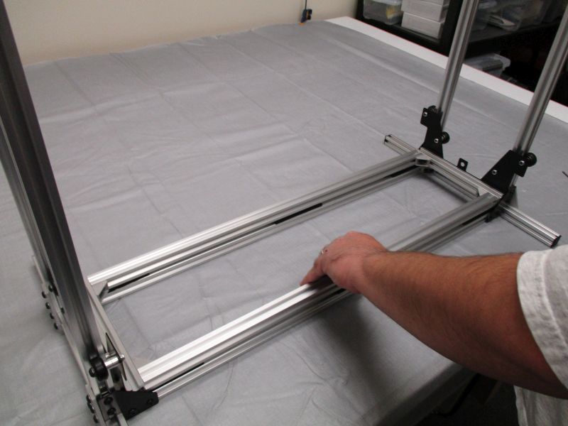
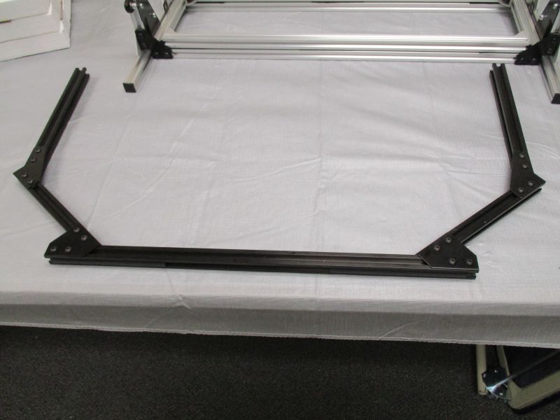
Gather Platen Front and Back.

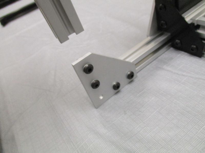
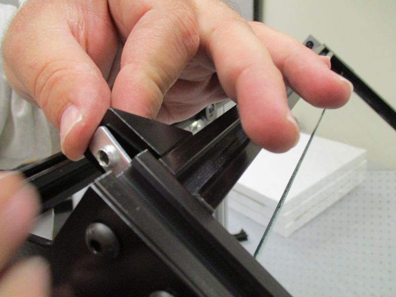
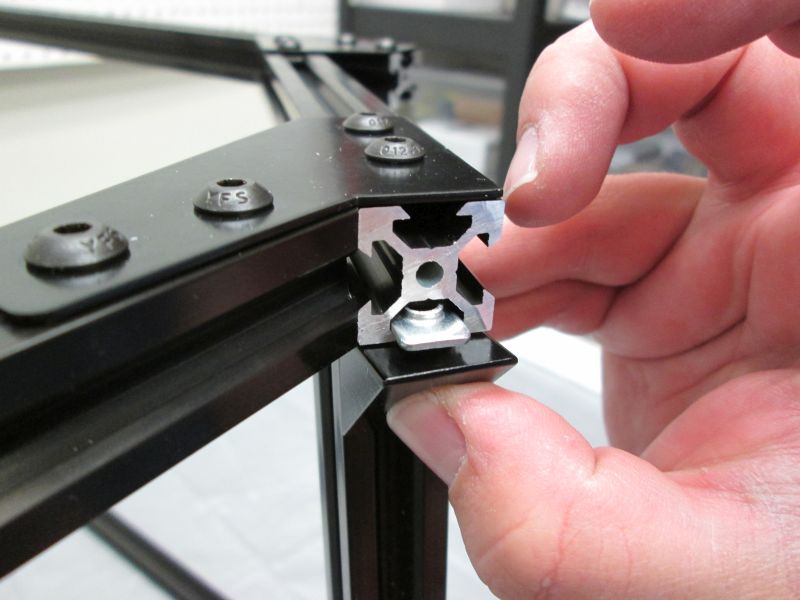
Slide L-Plates onto Black Cross Beam Sides.
There should be a gap big enough for one T-Slot beam to attach to both the Corner Bracket and Side Plate.
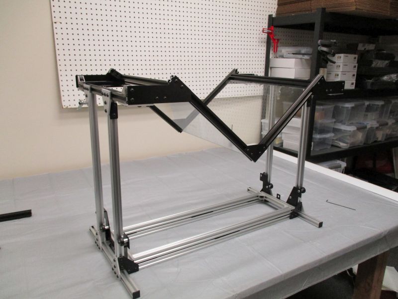
Turn Platform Assembly around. Attach Platen Back
Both Platen Front and Back are now approximately placed.
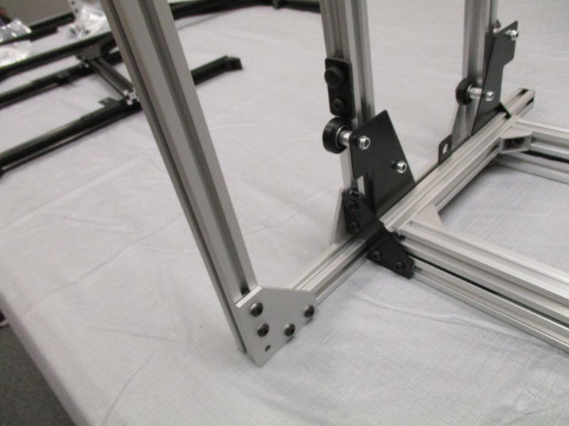
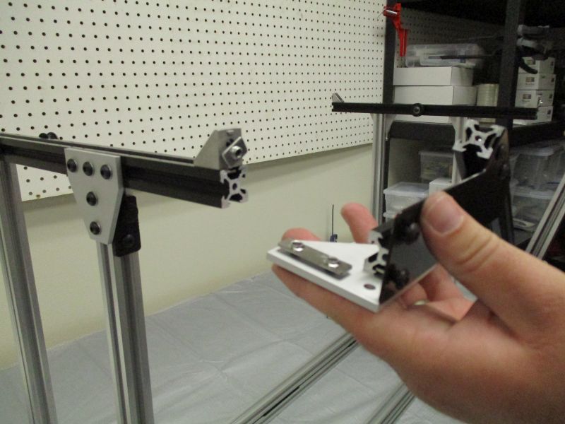
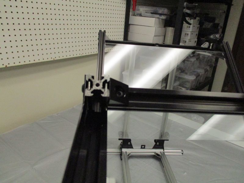
Gather the Imaging Module Back. This is the one without Pulleys.
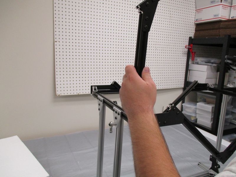
Slide an Imaging Module Column onto both the Corner Bracket of the side and the Side Plate of the back.
Repeat with other side.
Snug the screws of the Corner Brackets and Side Plate. Tighten all the screws of the L-Plate. The Platen Back is now fixed in the correct position.
Loosen the screws connecting the Corner Bracket and Side Plate to the Imaging Columns. Remove the Imaging Bracket.
Repeat this process to tighten the L-Plates of the Platen Front into the right position.
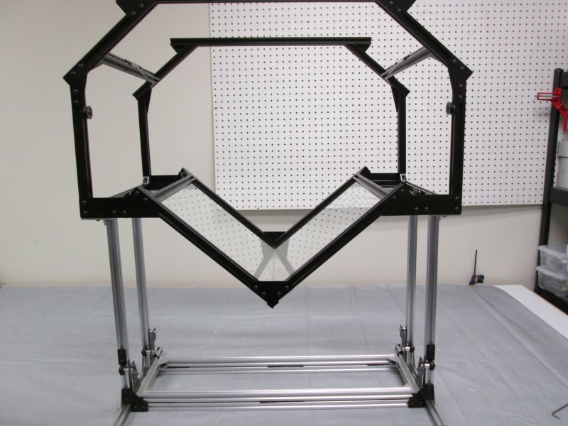
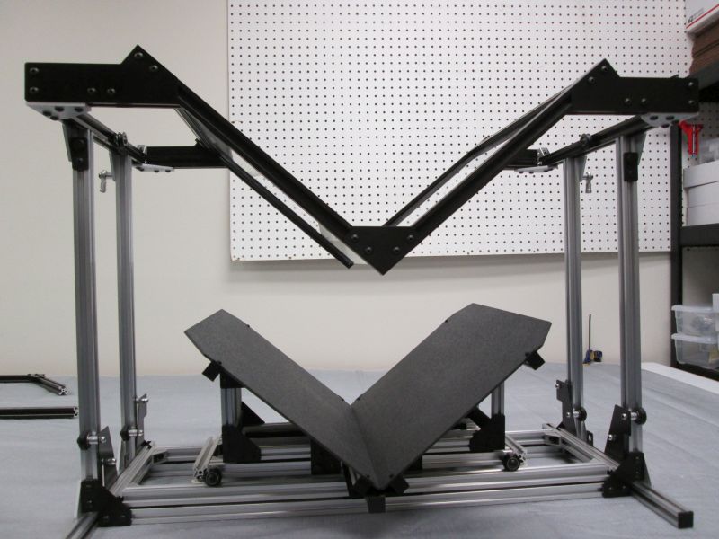
Insert Glass Plates
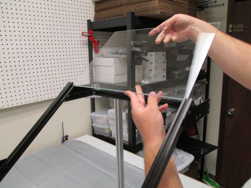
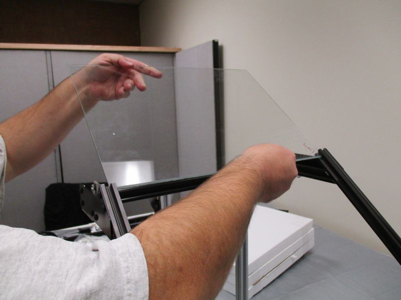
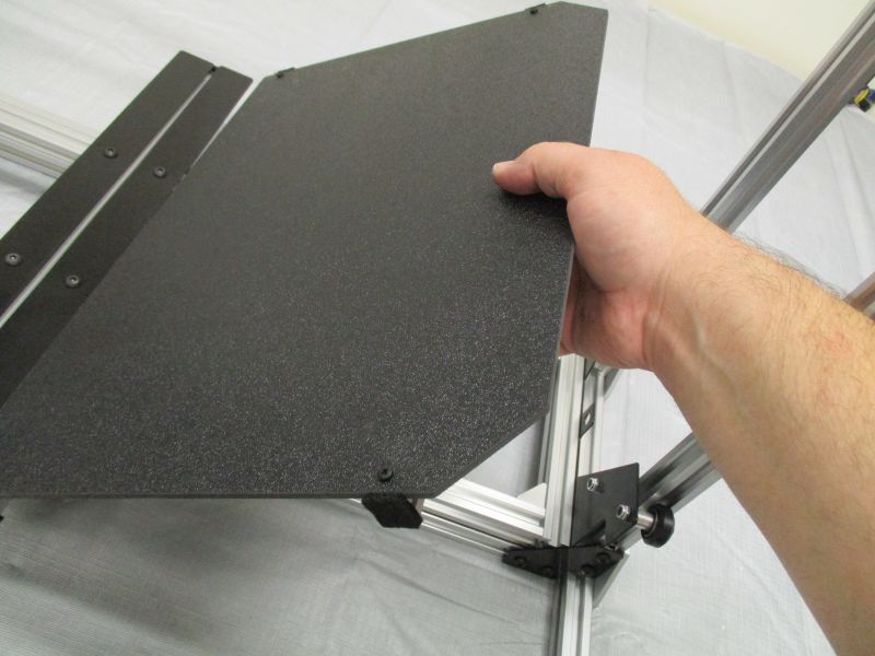
Take a glass plate from its protective packaging. Find the mitered edge. Be careful as it may be sharp. Carefully slide the glass between a pair of Glass Holders with the pointed edge at the bottom.
Carefully slide the Glass Plate inside of the Glass Slot Cover.
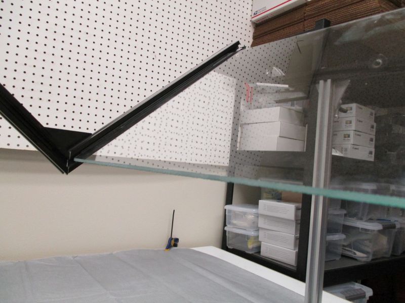
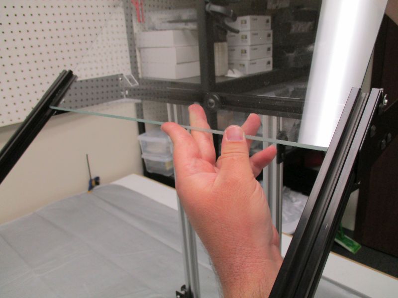
Guide the glass to the bottom of the connection. Let it rest gently there.
Repeat on other side.
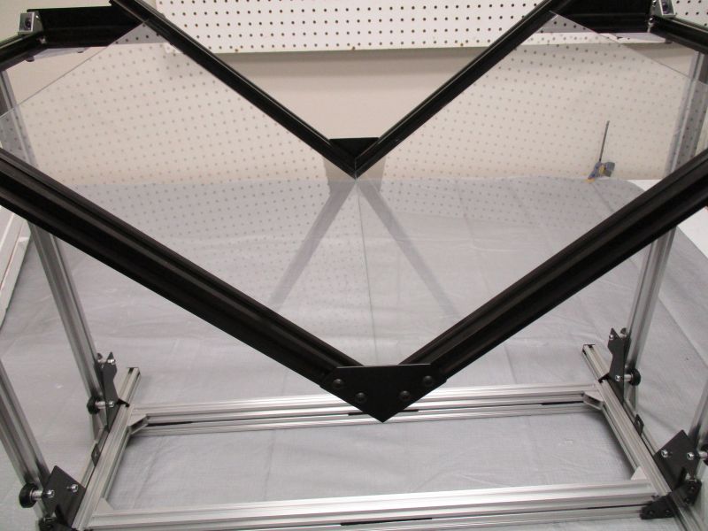
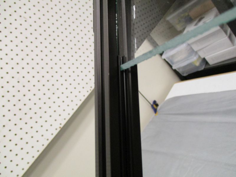
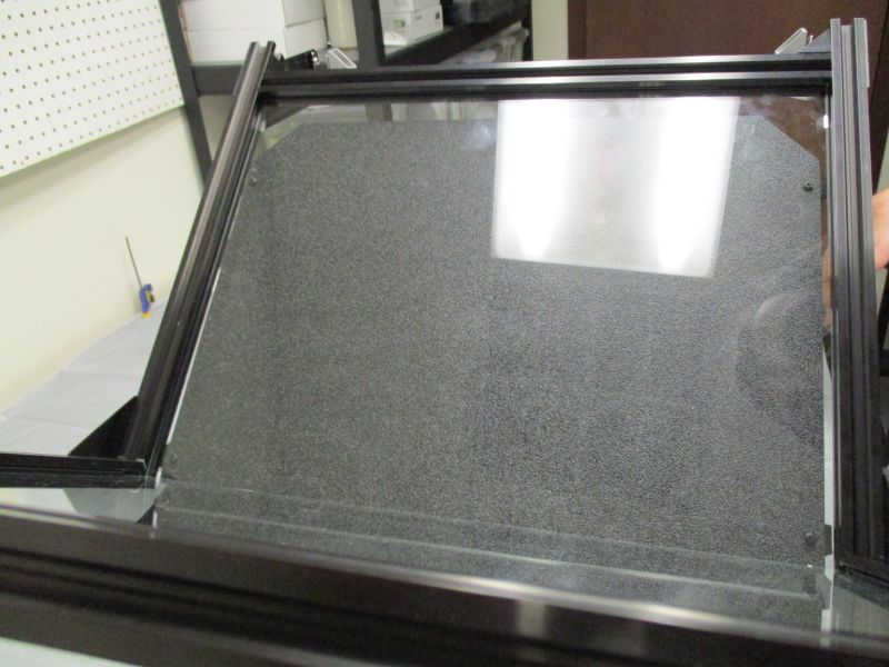
Adjust the positioning of the Glass Plates where they meet so that the mitered edges mesh and minimize the size of the gutter.
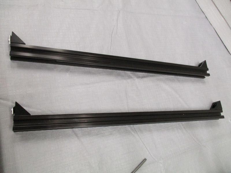
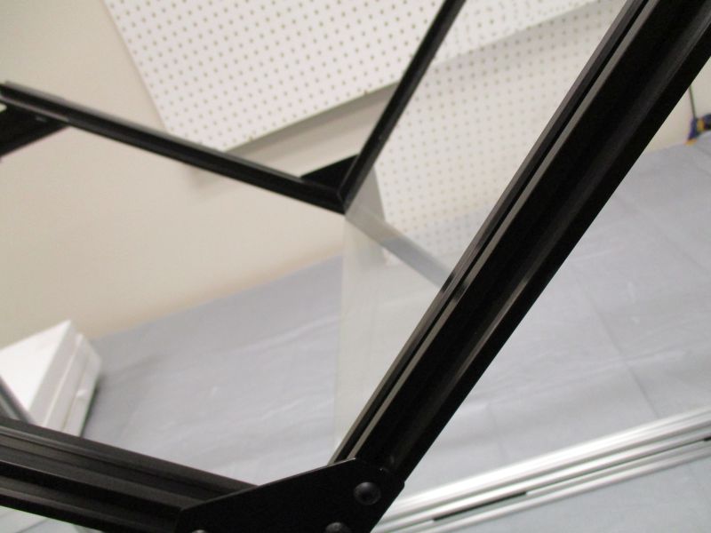
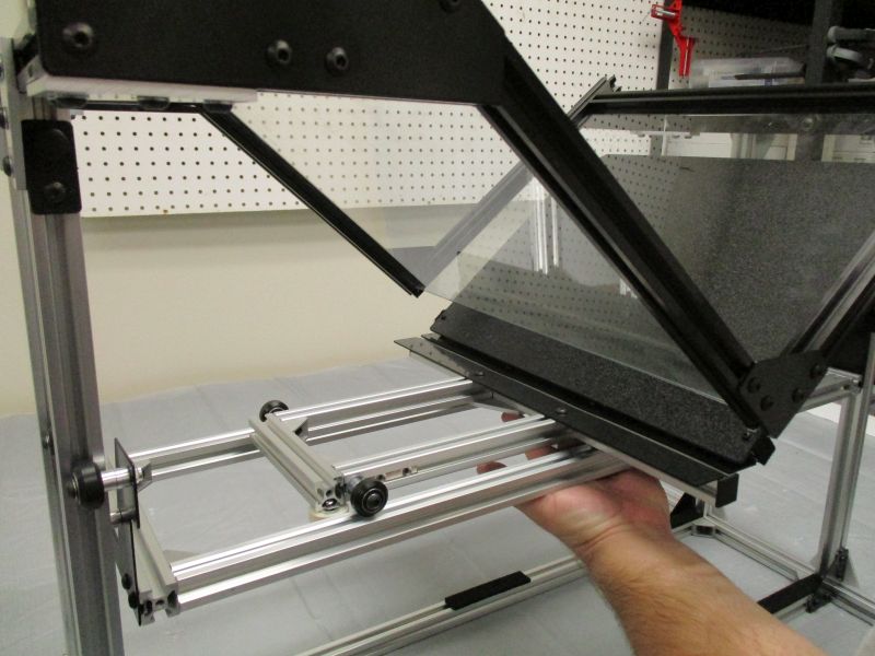
Gather the Black Cross Beam Middles from the Platen Assembly.
Slide a Black Cross Beam Middle between the two Glass Holders. The Black Corner Brackets face away from the Glass Plates and the Glass Slot Cover inside faces towards the Glass Plates.
Repeat on the other side. When the Glass Plates are in their final position, tighten the (4) Black Corner Brackets into place.
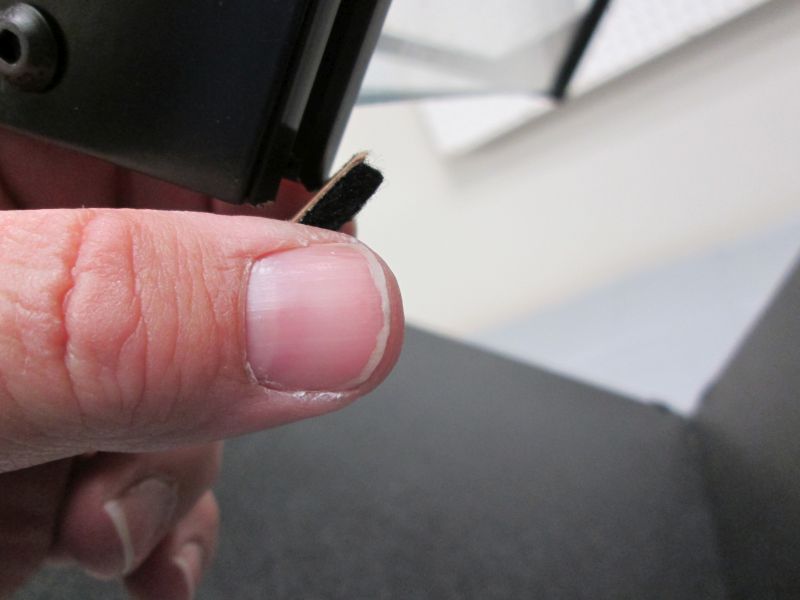
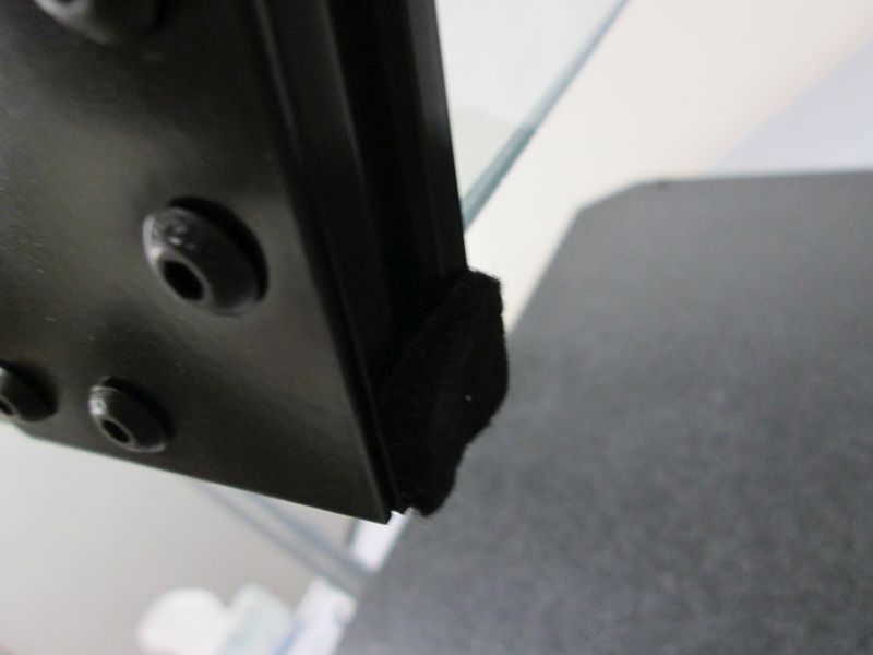
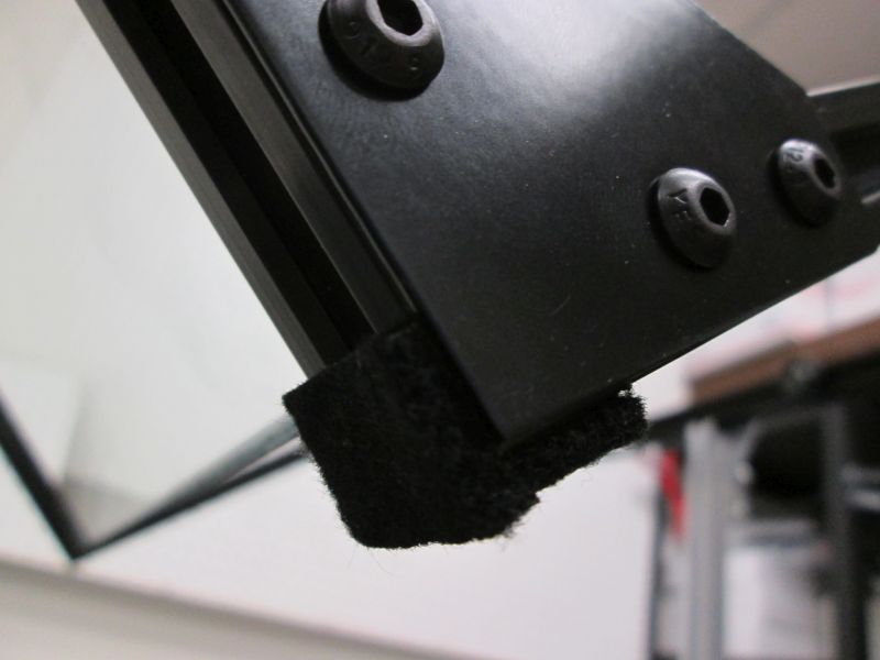
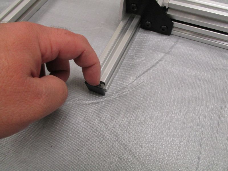
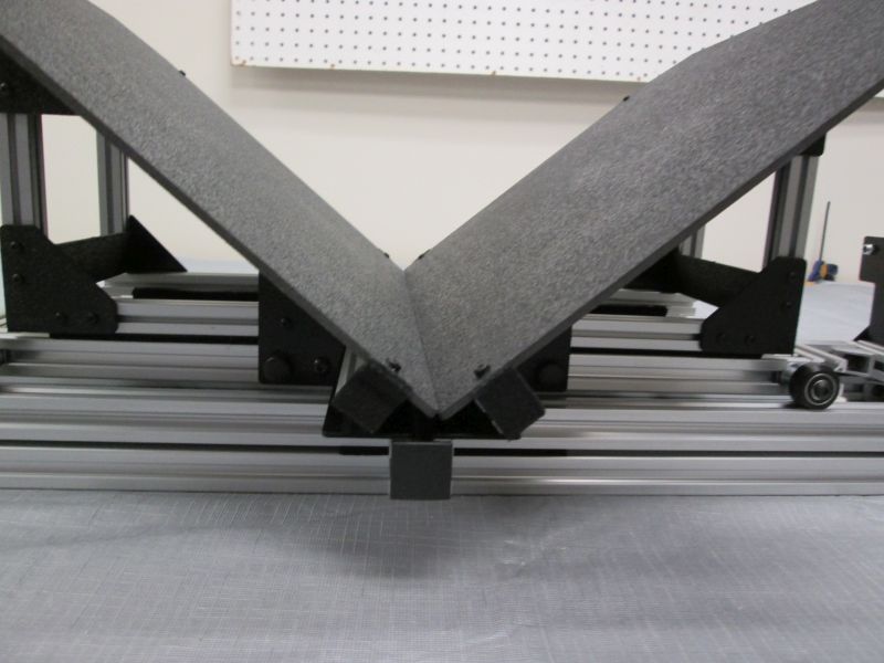
Attach felt end caps to the bottom of the 'V' to cover the pointed ends of the extrusion. Use two on the front and two on the back.
Attaching Cradle Base and Cradle Wings
Place Cradle Base on Cradle Lifter.
Adjust final position of the Felt Bobs on the Cradle Base.
Felt Bob must be far enough back to let the V-Wheel ride in the V-Slot. But it must touch the rail to provide friction.
Ensure that the Cradle Base moves back and forth smoothly along rail. If it tends to derail then the Cradle Base is not square or the Cradle Lifter is not square. Adjust if necessary.
Place Cradle Wing on Cradle Base. The two plastic tabs on the sides lie on either side of the Base Struts.
Raise Cradle Assembly towards the glass. The Cradle Wing Plate should be able to rest against the glass between the two Glass Holders. If not, then loosen the two screws on each Cradle Angle Beam that holds the Cradle Wing Supports in place. You can shift the whole cradle plate one way or another until it does. Tighten the Cradle Angle Beam screws.
Gather (2) M5 Finger Clamps and (2) M5 x 8mm Screws from Cradle Wing kit.
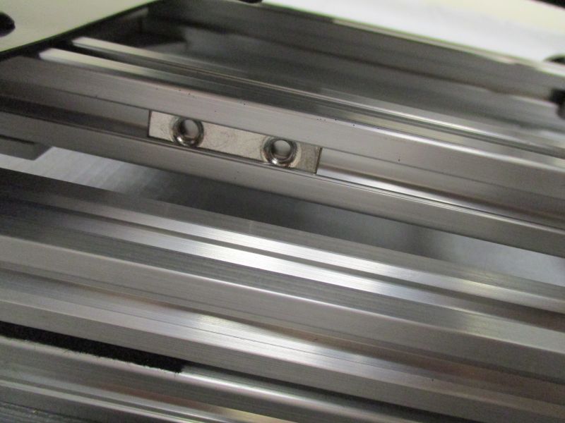
Look for the captive Double T-Nuts on either side of the Cradle Base.
Align tabs with a Double T-Nut.
Screw an M5 x 8mm Screw into the side of the Double T-Nut closest to the middle. Leave this screw permanently loose.
Screw M5 Finger Clamp into the other side of the Double T-Nut. Loosen and Tighten it as necessary to move Cradle Wing.
Repeat on the other side of the Cradle Wing.
Repeat for other Cradle Wing.
Attach Imaging Module
Slide Imaging Module Front onto Platen Assembly. The Pulleys on the Imaging Module should be on the same side as the Cradle Stops but the opposite side as the Rod Ends.
Repeat with Imaging Module Back. Snug screws on Side Plate and Corner Brackets.
Move the Cradle Stops to the bottom position and tighten them into place. Set aside the Cradle Base for a moment.
Turn the Archivist Quill on its side. The next steps are much easier if gravity is not working against you.
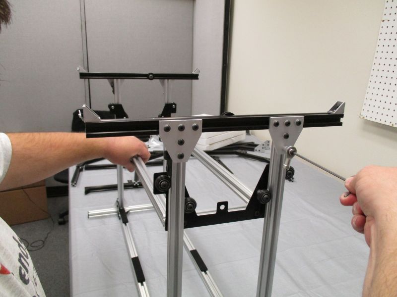
Slide a Black Cross Beam onto an Imaging Strut.
Slide the bottom of the Black Cross Beam onto the other Imaging Strut. Snug the screws on the Black Corner Brackets.
Repeat on the other side.
Now you can adjust position and ensure that the Black Cross Beams are flush by loosening and tightening just a couple of screws at once.
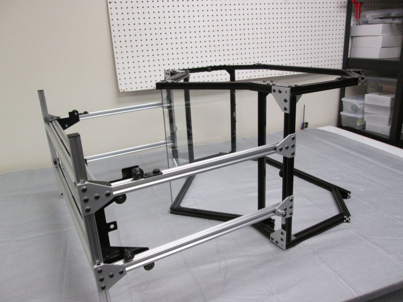
Place scanner right side up. The main structure is now complete. Tighten all screws.