Lighting Module
Special Notes
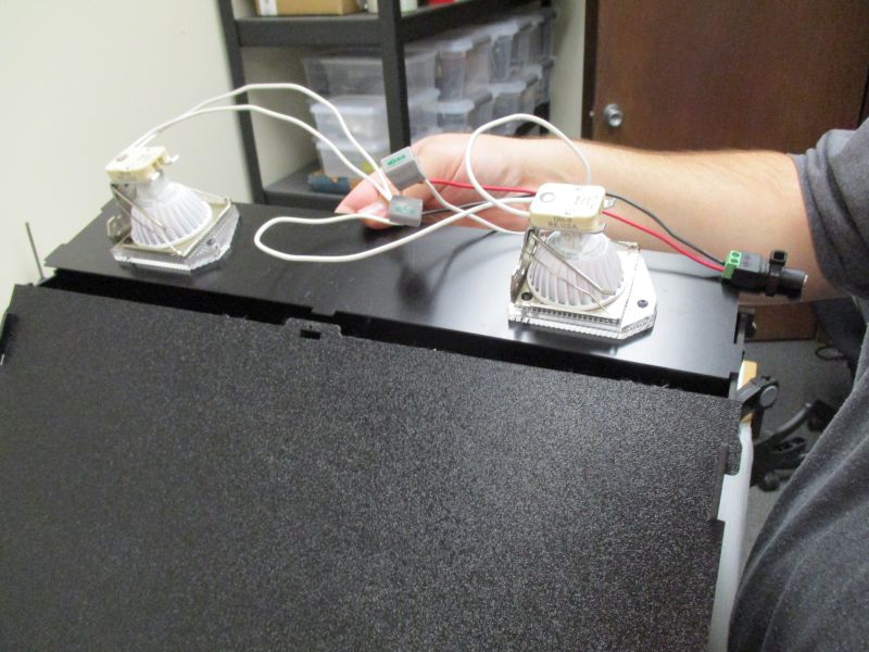
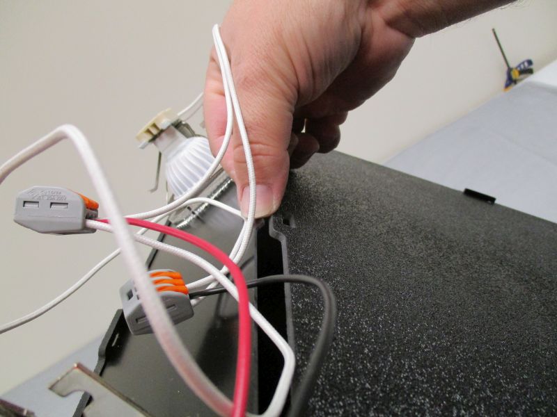
Before assembly, plug in the LED Bundle using the LED Power Supply and Cable to ensure that they are working correctly. If they are not working correctly, make sure that the LED bulbs are firmly seated in their sockets and check the wires in the LED Bundle to make sure none have come loose.
Inventory
Tools needed:
- 2mm Hex Key (in Tool Bag)
Parts needed:
- (1) Lighting Module Bag
- (2) Lighting Module Front
- (2) Lighting Module Side
- (2) Lighting Module Small Baffle
- (2) Lighting Module Large Baffle
- (2) Lighting Module Door
- (1) LED Base Plate
- (1) LED Bundle
- (1) LED Power Supply and Cable
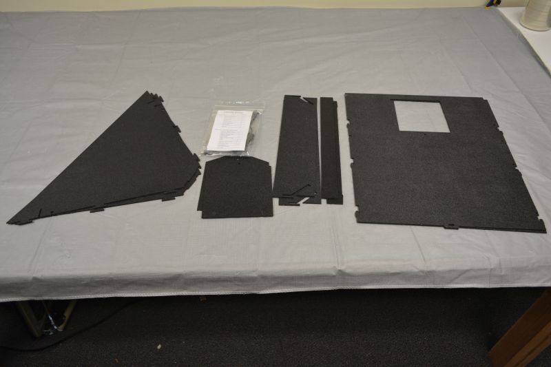
Gather parts together. Use the part list in the Lighting Module Bag to verify that all parts are present before beginning. Notify help@tenrec.builders if any parts are missing.
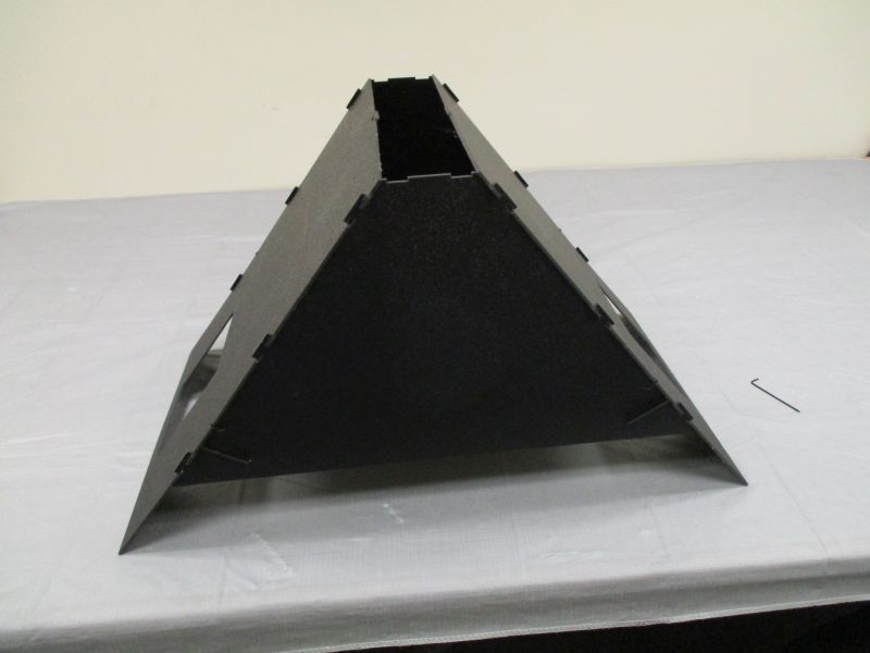
Assemble Lighting Module Front Pieces
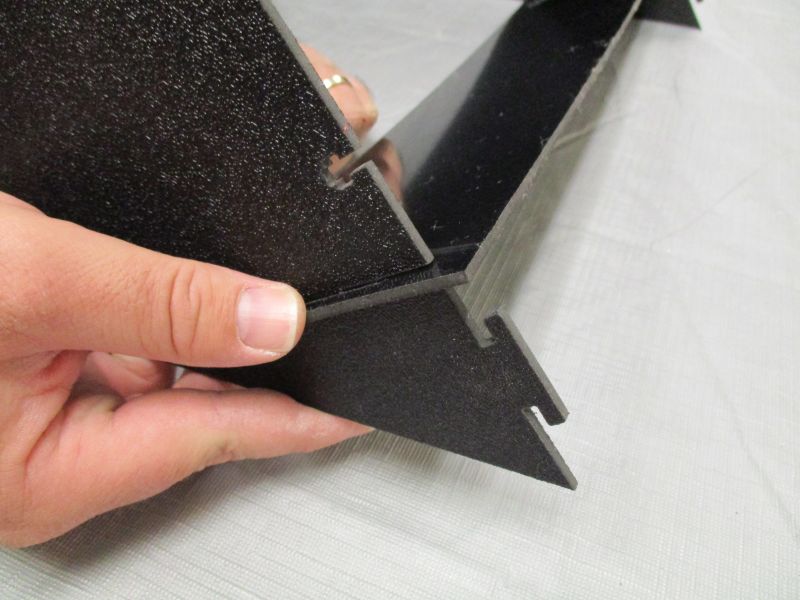
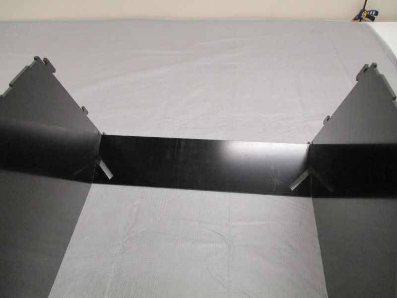
Insert the slots of a Lighting Module Large Baffle into two Lighting Module Front slots. The glossy side should be on top.
Repeat with the other Large Baffle
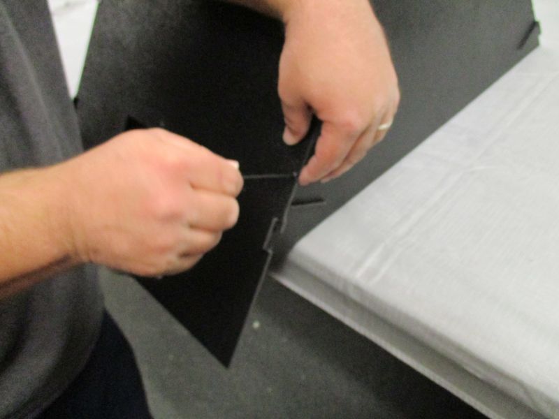
Insert a Small Baffle into the slot of a Large Baffle. The shiny side should be up. The smooth edge will lie against the Front Plate. The bumps on the opposite edge will help hold it in place against the Large Baffles.
Push the Small Baffle through the slot until it sticks out from the assembly.
Pull Small Baffle back along the Front Plate and feed it into the slot of the Large Baffle on the other side. The two bumps along the edge of the Small Baffle should rest against the edges of the slots to help keep it in place.
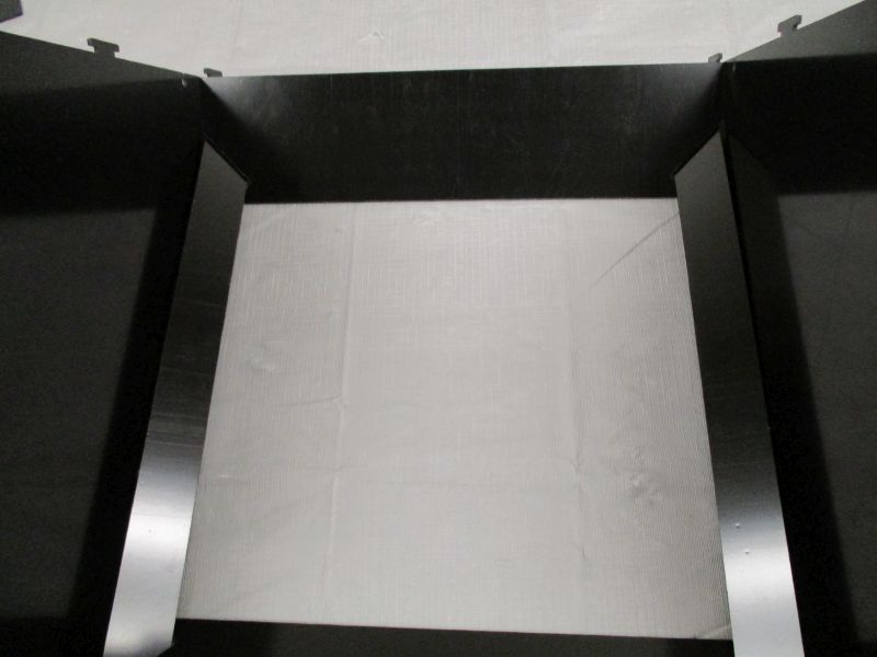
Repeat with other Small Baffle.
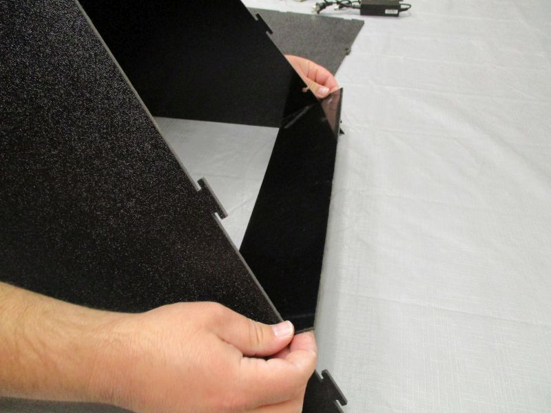
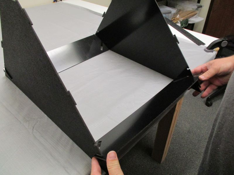
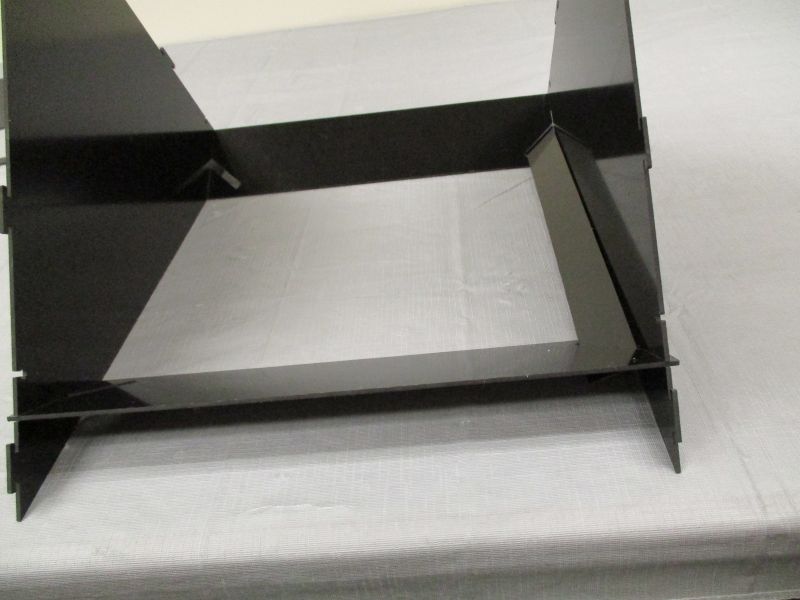
Attach Side Plates
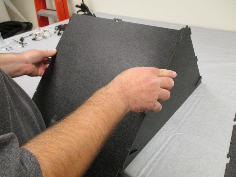
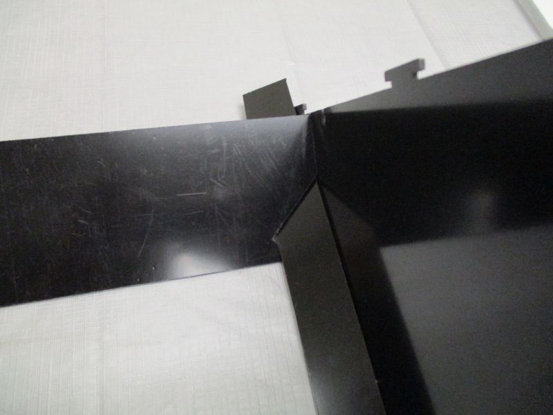
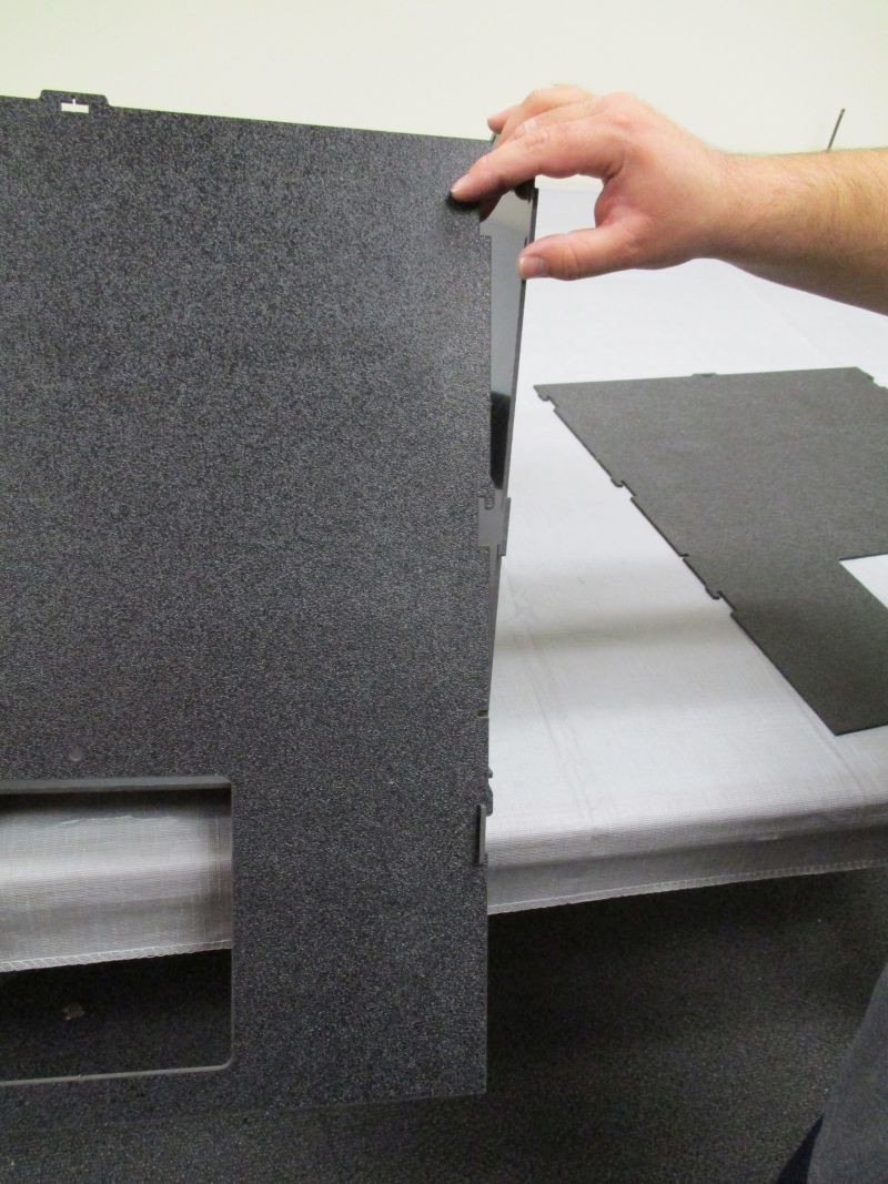
Place assembly at the edge of a table. Align Side Plate against two Front Plates. The small slot goes on top while the large square hole goes at the bottom. The rough side is on top while the shiny side is on the bottom.
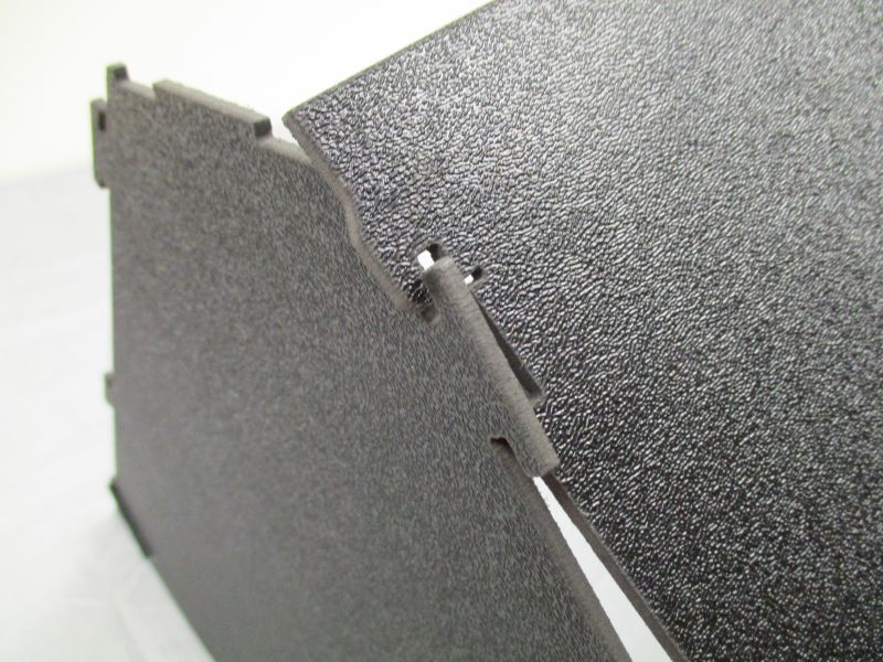
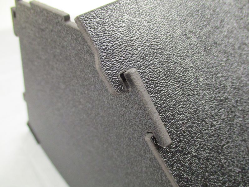
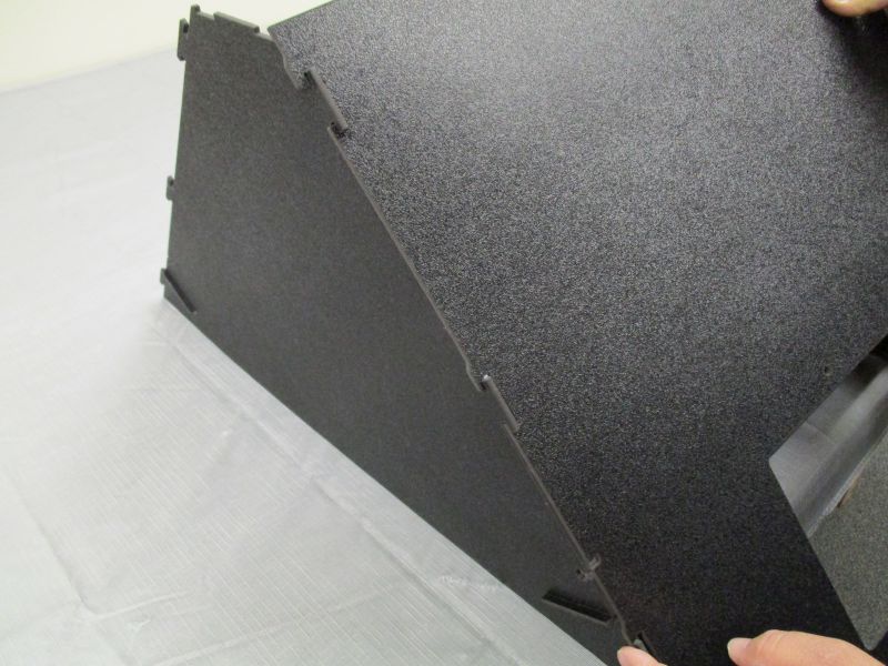
Starting at the left side side, gently work the slots on the side plate around the tabs on the side plate. For the first side, work from top to bottom. Do not pull down to lock them yet.
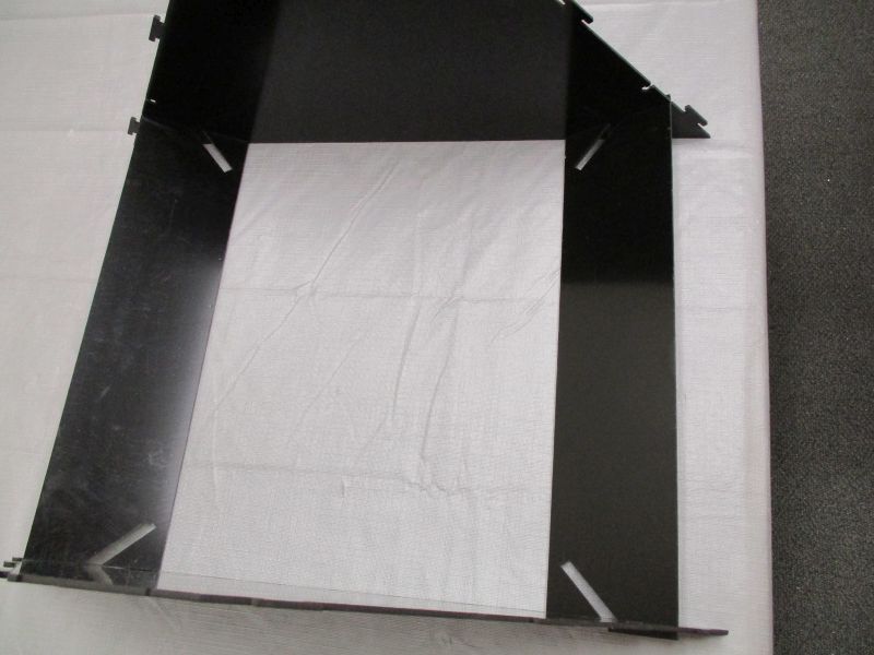
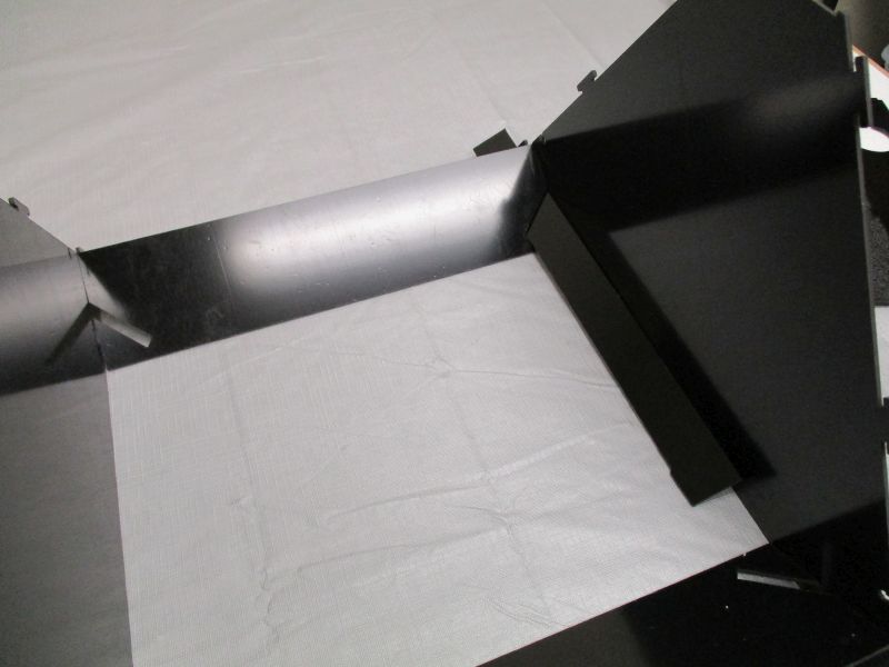
Starting at the bottom, insert the tabs on the right into the slots. The bottom right corner will be the trickiest since it is most constrained. Once it is in place, the remaining slots should be successively easier.
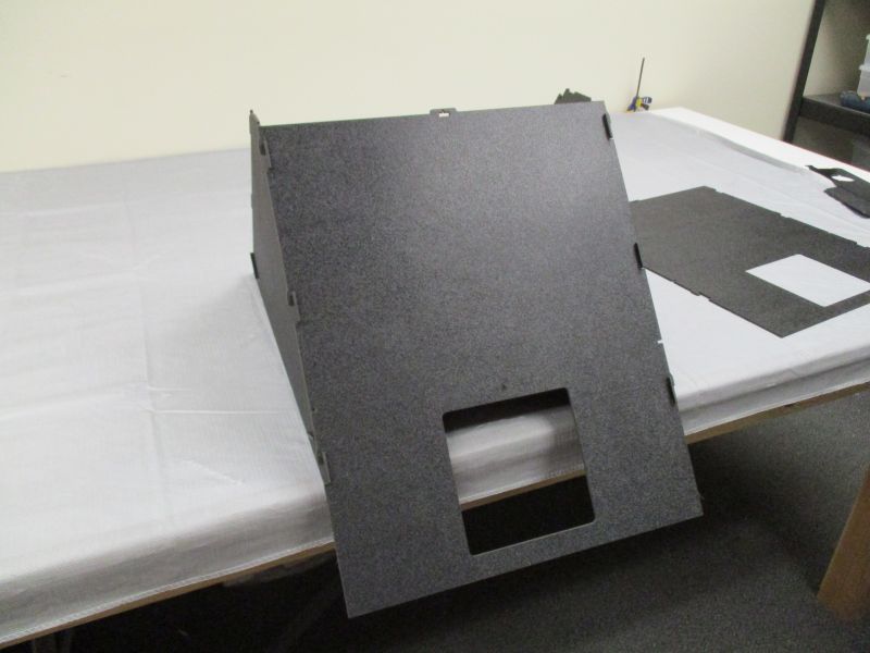
Once all slots have been inserted, pull down on the side plate until the tabs are at the bottom of their range.
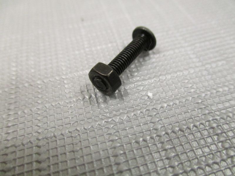
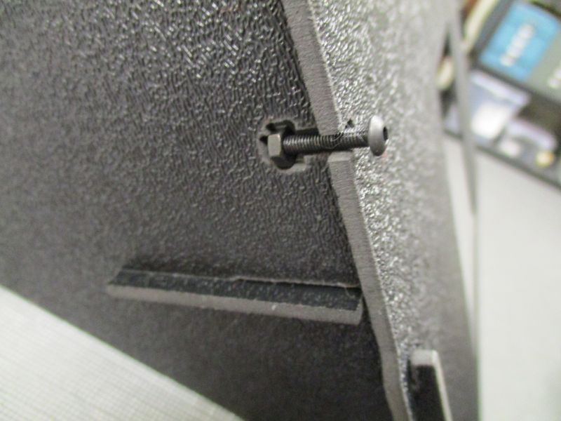
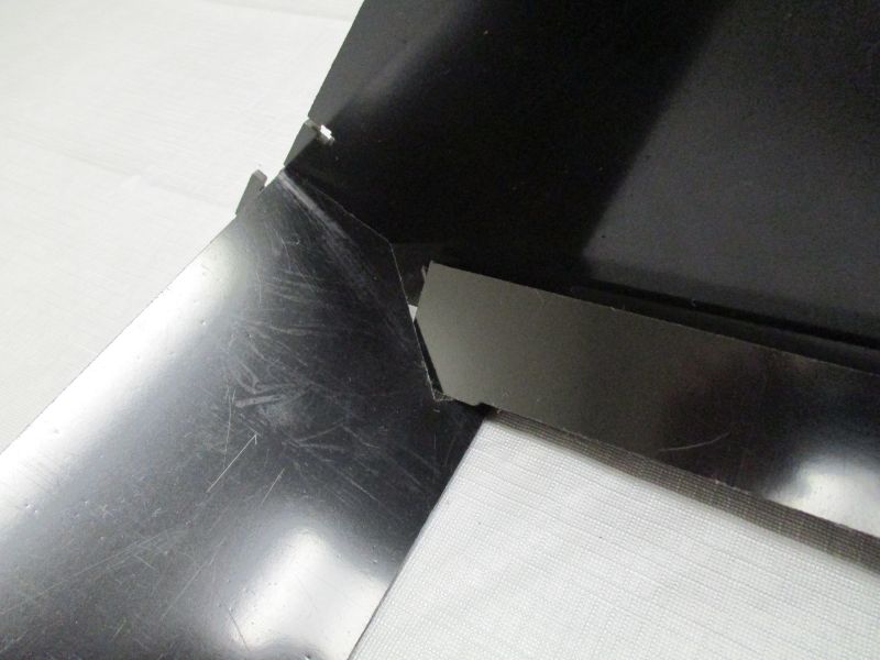
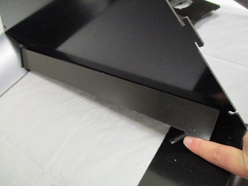
The small holes on each side of the Side Plate will now align with the cross-shaped tabs on the Front Plate. Thread an M3 Hex Nut onto an M3 x 14mm Screw and insert it into this hole from the side.
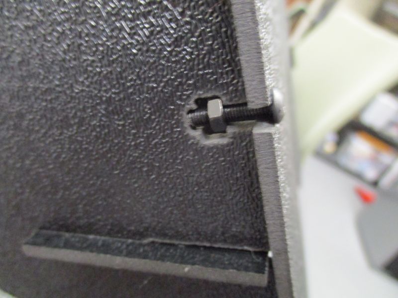
Hold the nut in place with your finger while you lightly tighten the screw.
Repeat on other side.
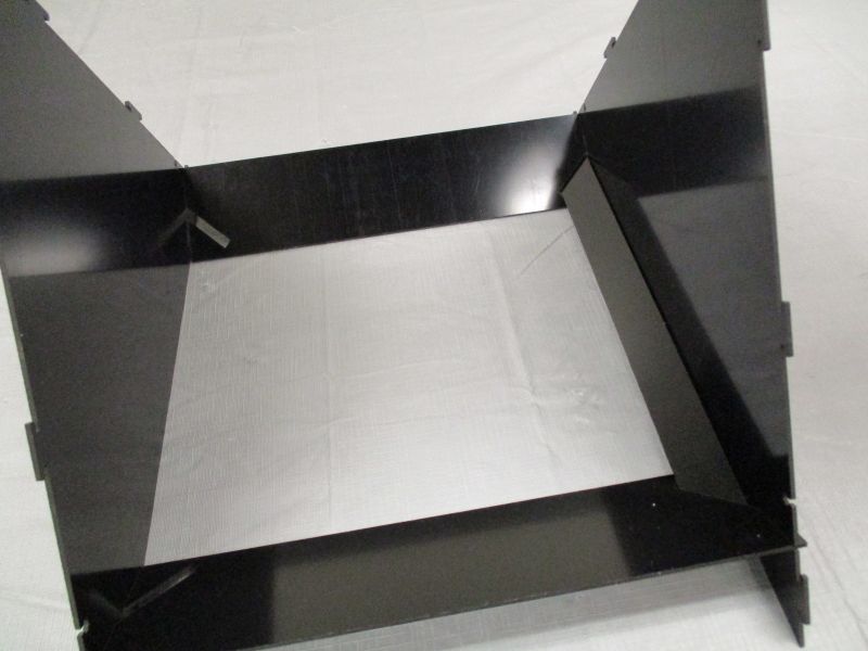
Attach the second Side Plate in the same way.
Attach Camera Doors
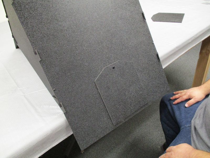
Align the hole of a Camera Door against its fellow on a Side Plate.
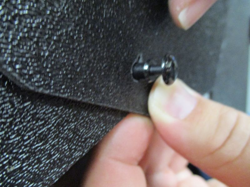
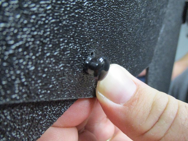
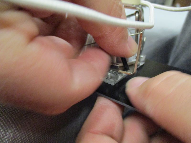
Insert a plastic rivet through both holes. Be careful to slide it loosely in until the shoulders are resting against the Camera Door.
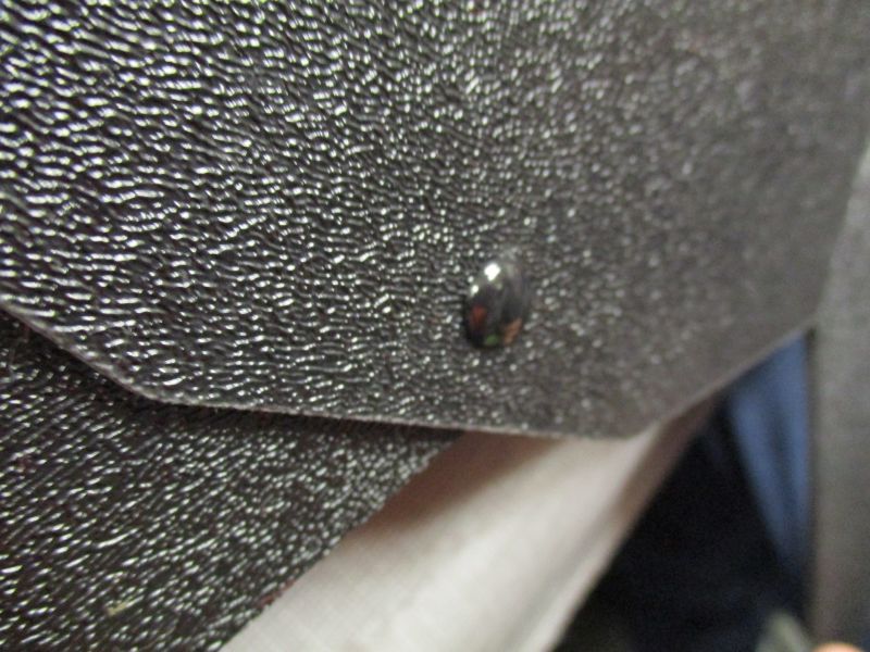
Press down on the top of the rivet with your thumb to lock the rivet into place.
The Camera Door is now firmly attached but can pivot freely. Repeat with other Camera Door and Side Plate.
Assemble Lights
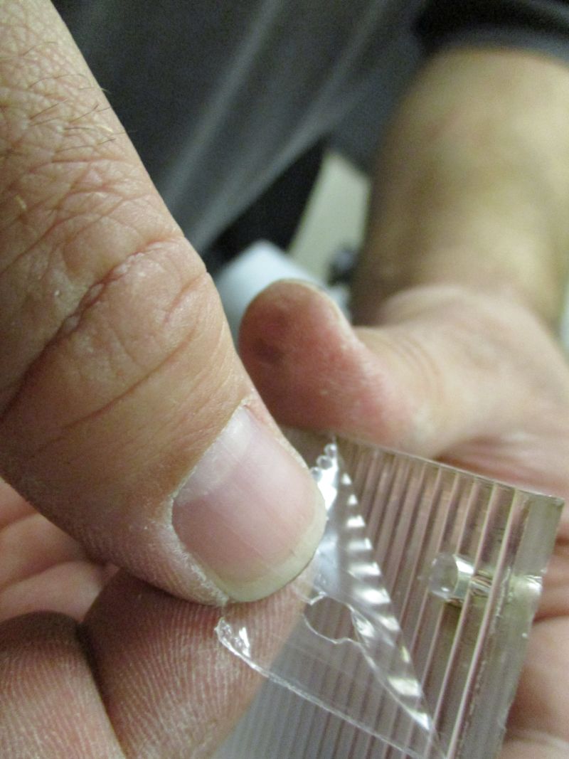
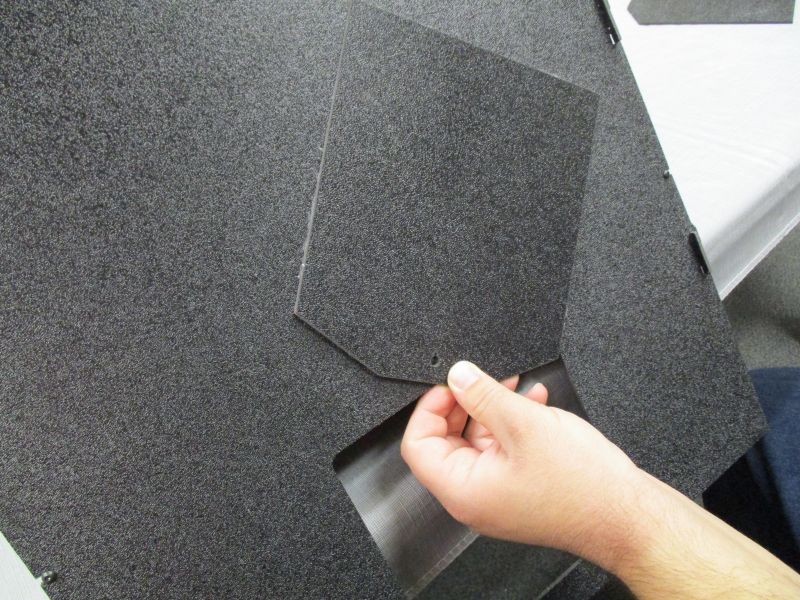
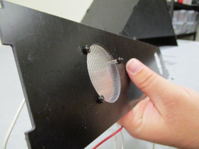
Remove protective plastic coating on both sides of each lens. If it is hard to get a purchase on a corner, use your fingernail to make a small hole in the coating in the center and then pull it off starting with the hole.
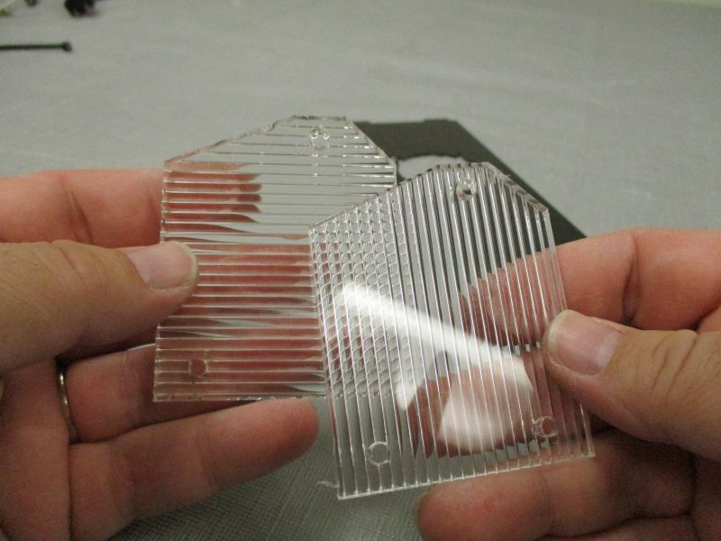
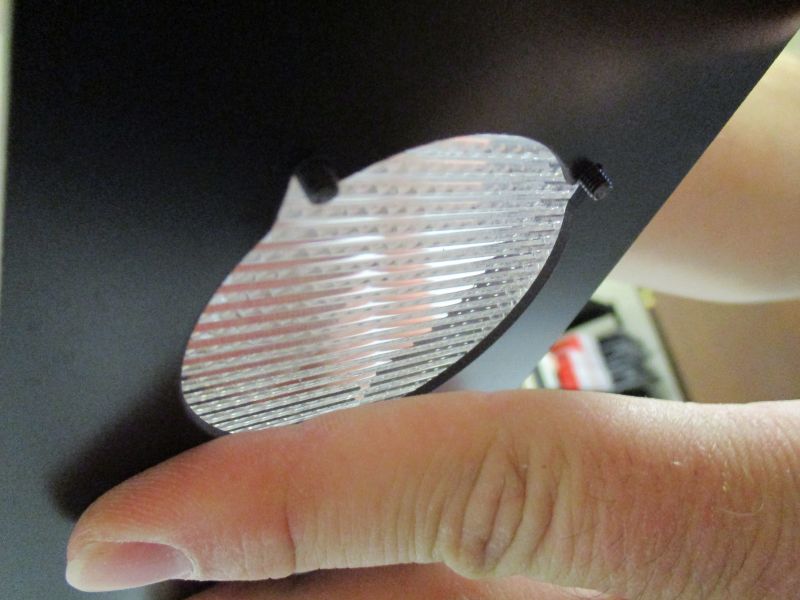
There are two Vertical Lenses which have ridges running along the long side. There are two Horizontal Lenses which have ridges running along the short side. Gather one of each kind of lens.
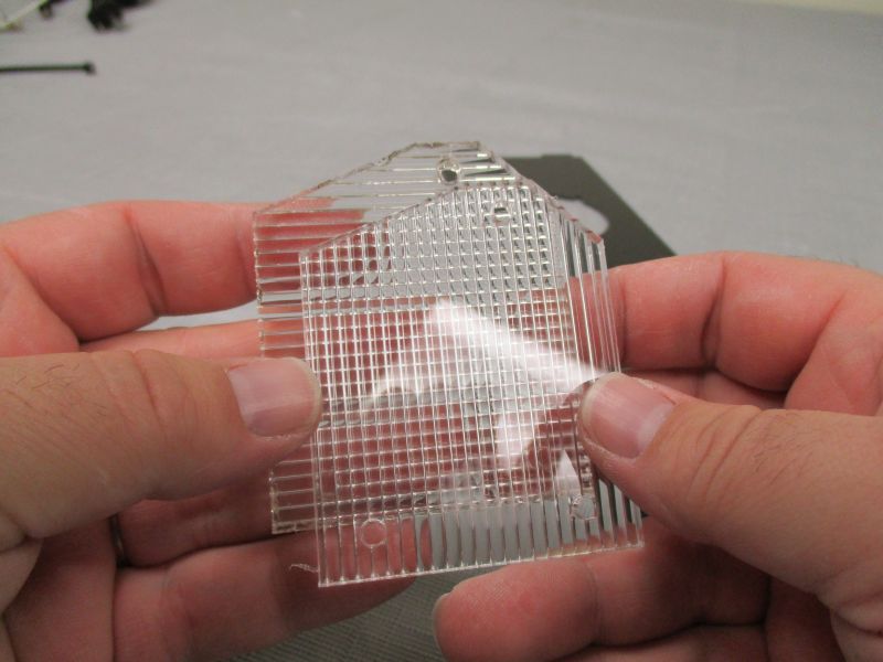
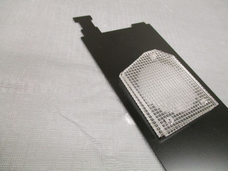
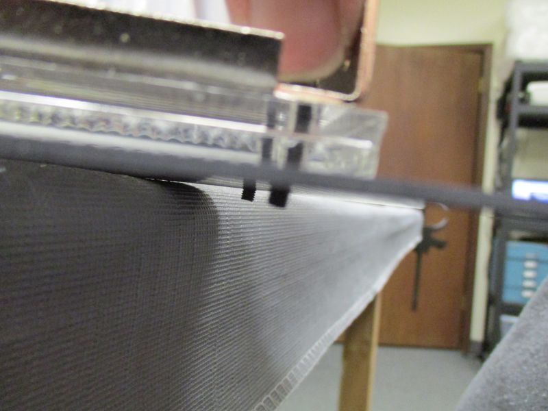
Stack the two lenses onto the LED Base Plate, aligning the holes. The Vertical Lens should be on top with the Horizontal Lens in the middle and the LED Base Plate on the bottom.
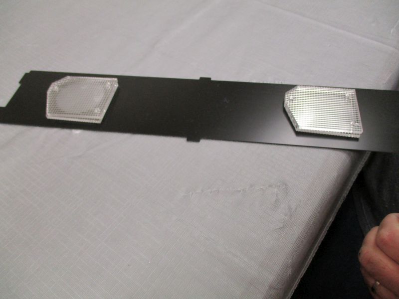
Repeat with other pair of lenses.
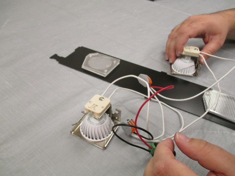
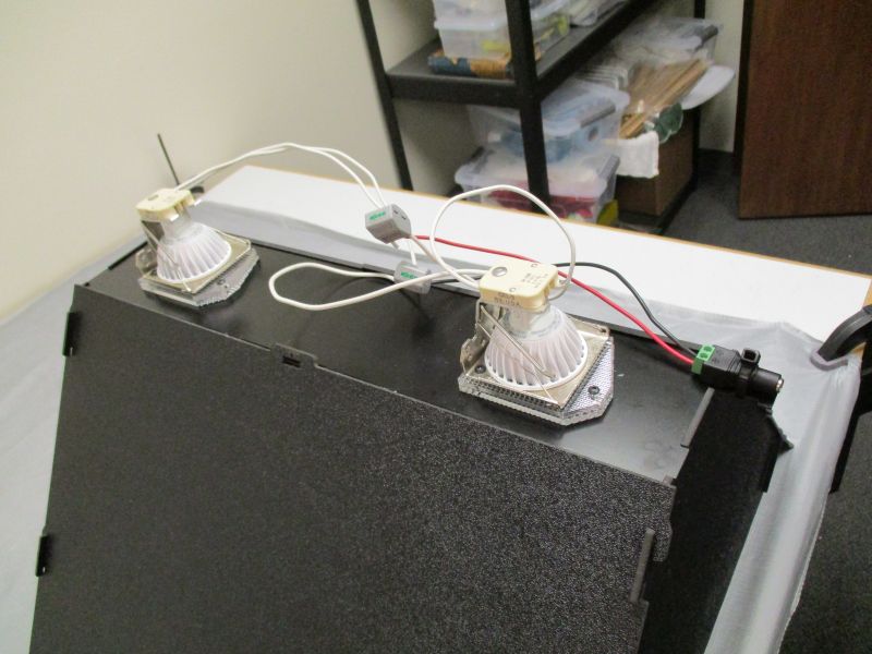
Gather LED Bundle. Each socket goes on top of one Lens stack.
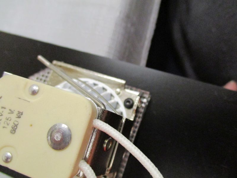
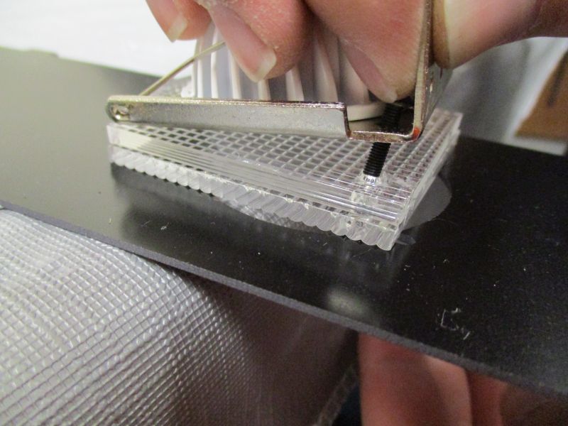
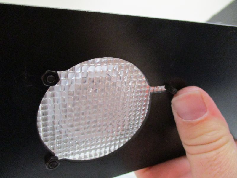
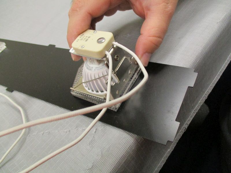
The LED sockets each have two holes which line up with the holes on one side of the lenses. Insert M3 x 14mm Screw into each hole, thread M3 Hex Nut onto the screw and finger tighten.
The third hole passes just through the two lenses and the LED Base Plate. Secure all three screws with M3 Hex Nuts.
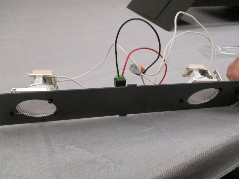
Repeat with other LED socket.
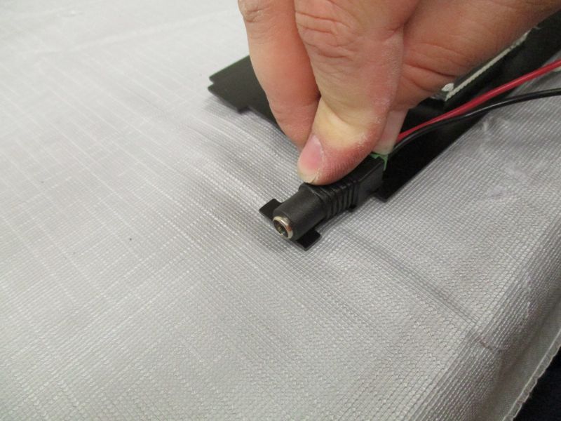
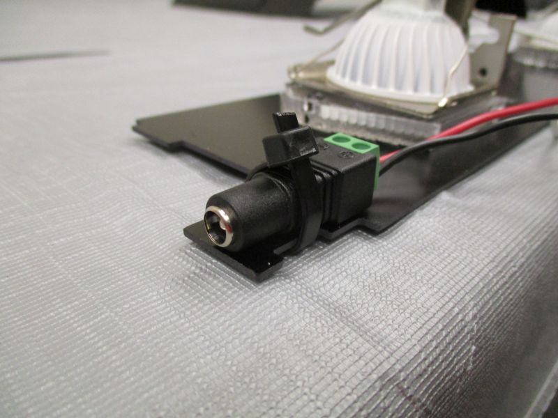
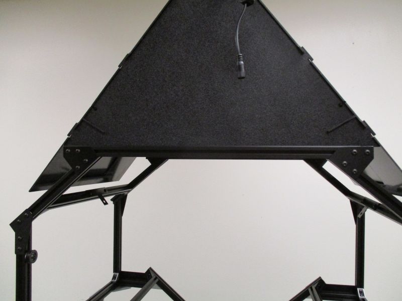
The barrel plug sits on the small tab that extends off one end of the LED Base Plate.
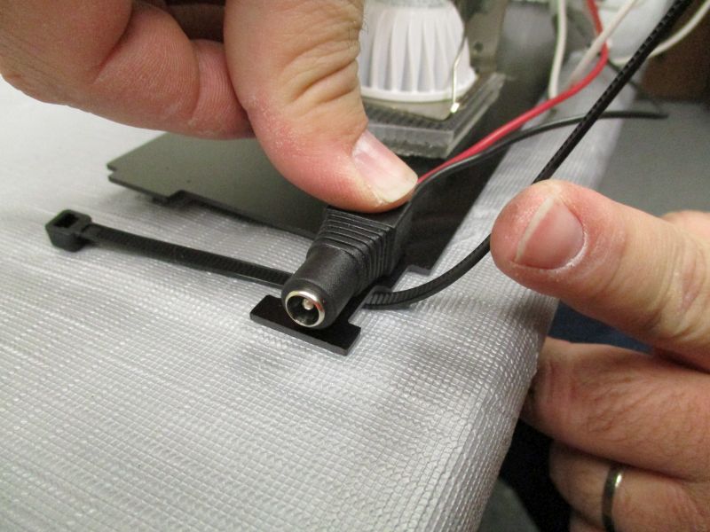
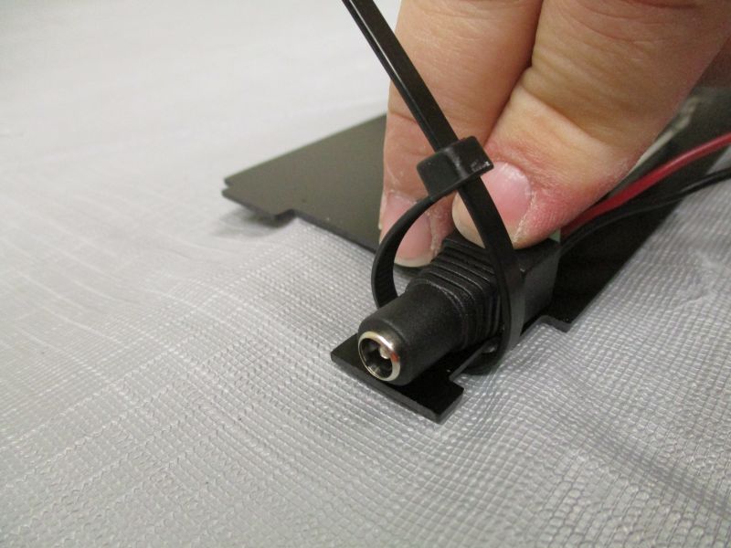
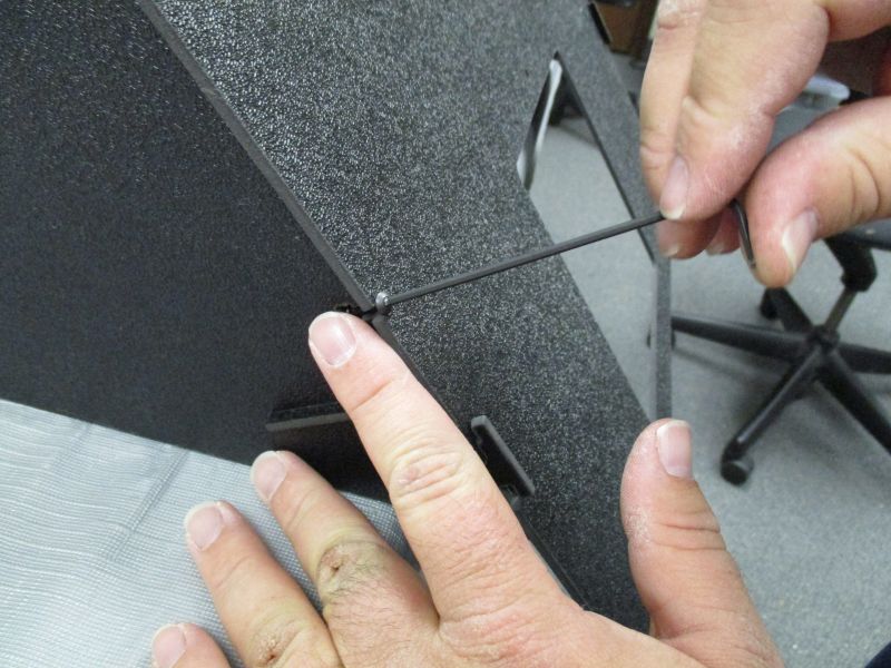
Secure the barrel plug with a zip tie around the narrow section of the tab. Cut excess zip tie plastic.
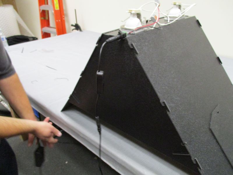
Final Assembly
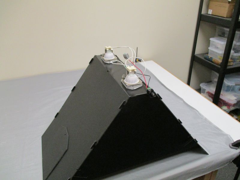
The LED Base Plate sits in the tabs on top of the Lighting Module Side Plates and Front Plates.
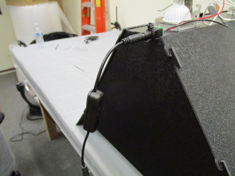
Plug DC Switch into barrel plug. This gives you an independent on/off switch for the lights. The lighting module can be mounted with the switch in the front (for convenience) or in the back (for tidiness).
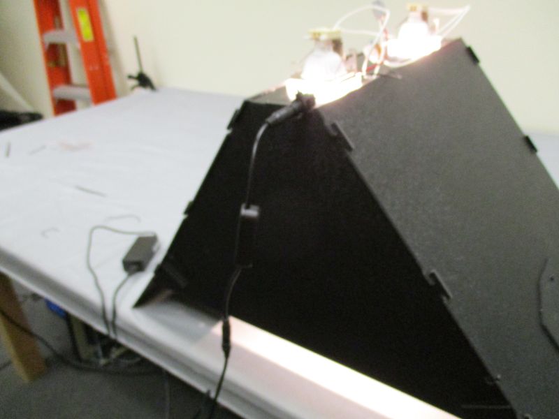
Plug in AC Adapter. Let there be light!
If the lights do not work, test the following:
- Turn off power before checking or adjusting wiring.
- Check to see if there are any loose or disconnected wires.
- Ensure that LED bulbs are properly seated in their sockets.
- Try removing the DC switch and plugging the AC adapter in directly.
- If the lights still do not come on, contact help@tenrec.builders for assistance.
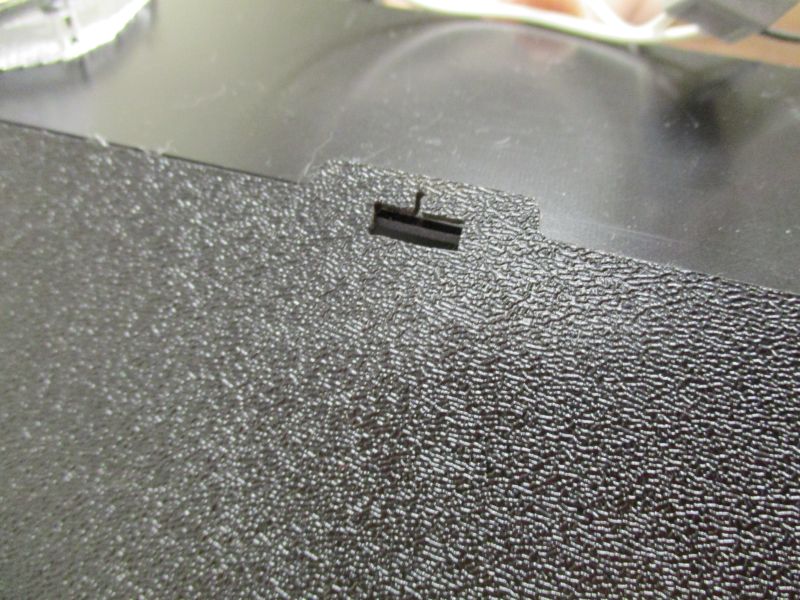
The lighting module rests on the inside edges of the Imaging Beams. Getting the placement just right can be tricky and an assistant may be necessary. The slot cover on top of the imaging beams helps keep the lighting module in place. Once in place, it simply rests on top with no need for further attachment.