Handlebar
Special Notes
Beginning in January 2017, Archivist Quill kits now contain a single handlebar beam. This is used instead of (1) long beam, (2) handlebar extenders, and (2) Strip Plates. Since the handlebar extenders don't have to be attached to the long beam, some of the steps below are not necessary.
Inventory
Tools needed:
- 3mm Hex Key (in Tool Bag)
Parts needed:
- (1) Handlebar Bag
- (1) Counter-Weight Bag
- (2) Clear Cross Beam
- (1) Long Beam
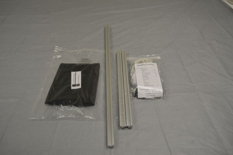
Gather parts together and remove plastic coating from extrusion pieces if necessary. Use the part list in the Handlebar Bag to verify that all parts are present before beginning. Notify help@tenrec.builders if any parts are missing.
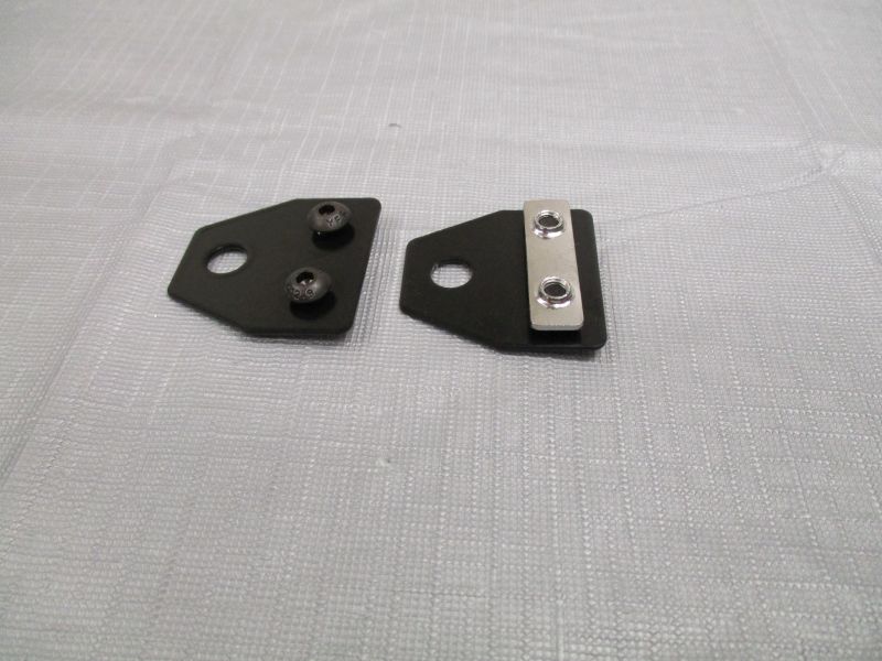
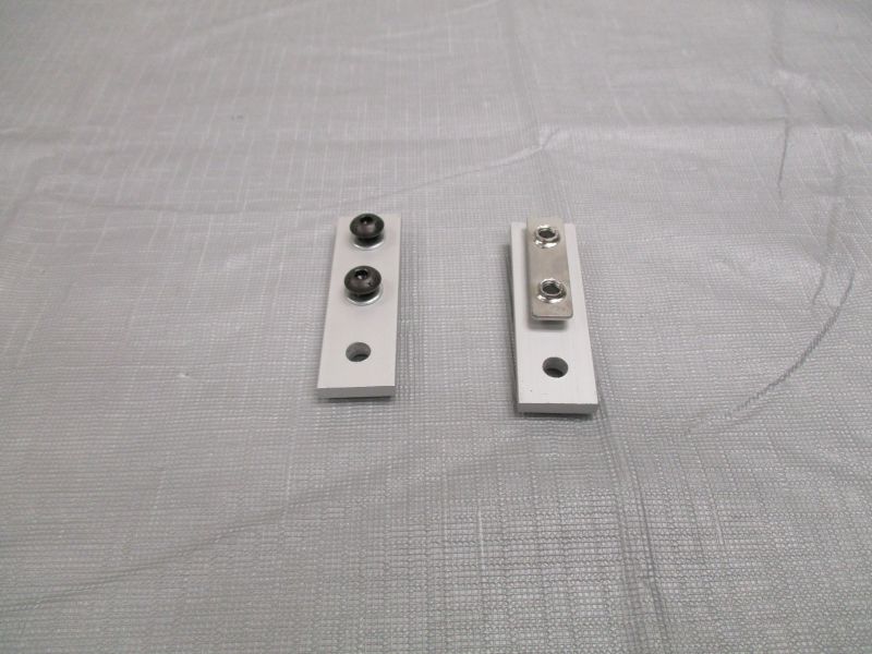
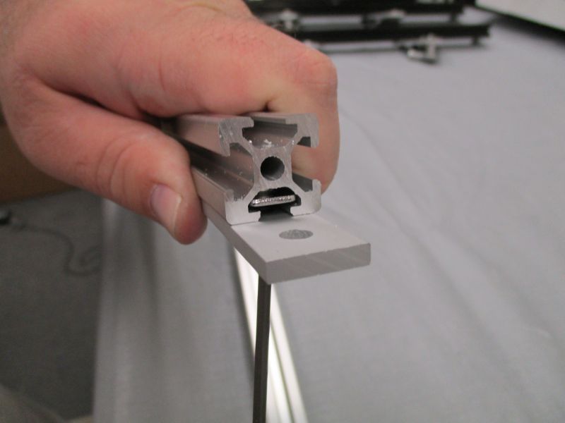
Preload (2) Rope Anchors
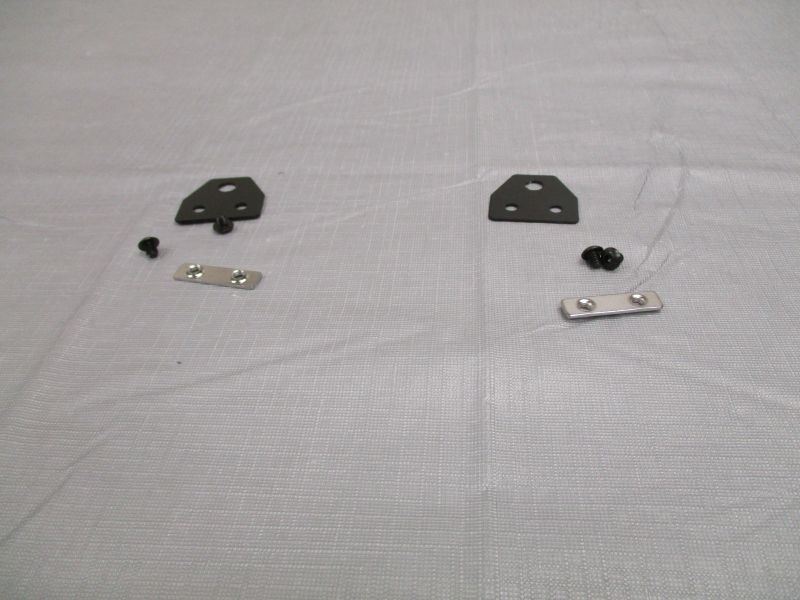
Each Rope Anchor uses (2) M5 x 6mm Screws and (1) Double T-Nut.
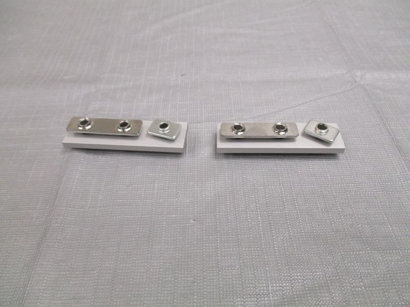
Preload (2) L-Plates
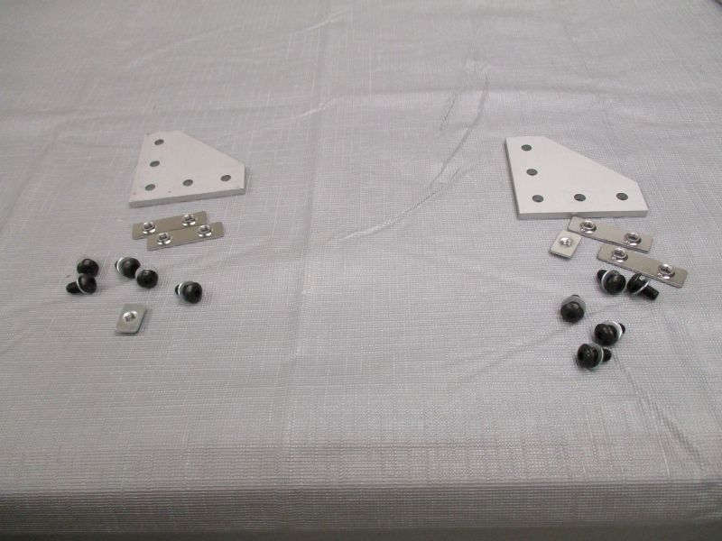
Each L-Plate uses (5) M5 x 10mm Screws, (5) M5 Washers, (2) Double T-Nuts, and (1) Single T-Nut.
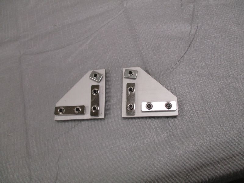
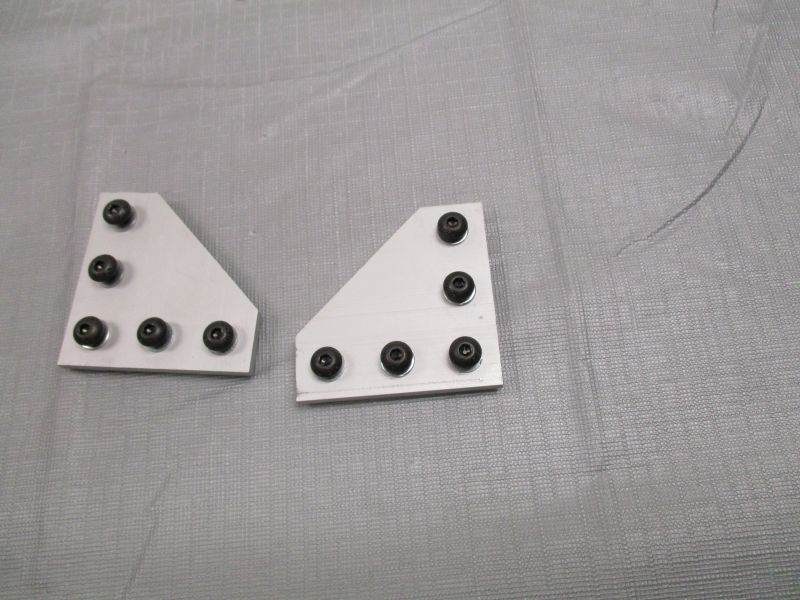
The configuration of T-Nuts on the two L-Plates should be mirrored to form a left/right pair.
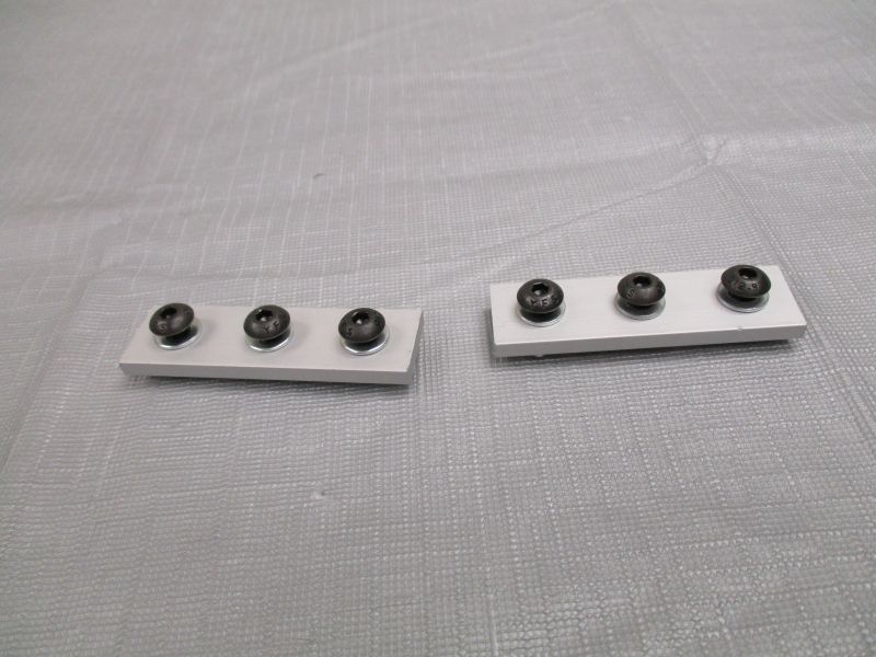
Preload (2) Strip Plates
Skip this step on kits sold in January 2017 or later.
Each Strip Plate uses (3) M5 x 10mm Screws, (3) M5 Washers, (1) Single T-Nut, and (1) Double T-Nut.
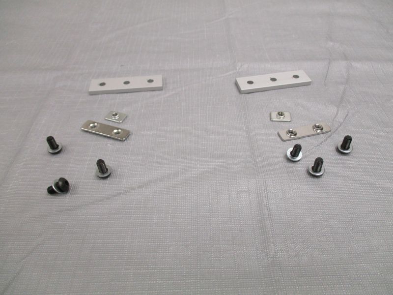
Preload (2) Strip Plates
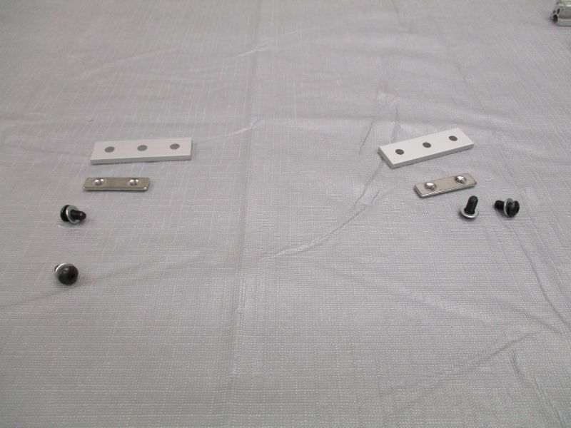
Each Strip Plate uses (2) M5 x 10mm Screws, (2) M5 Washers, and (1) Double T-Nut.
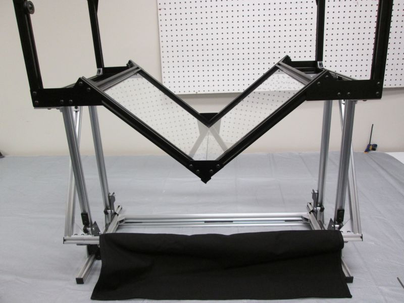
Assemble Handlebar
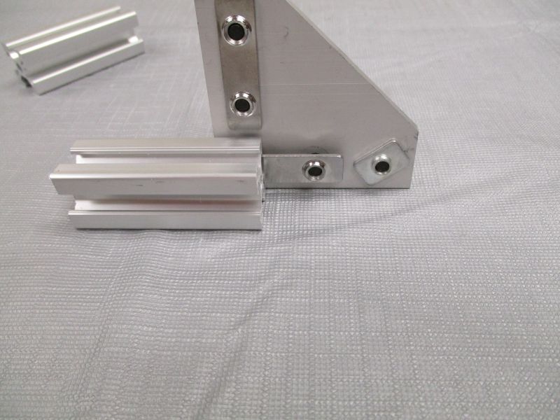
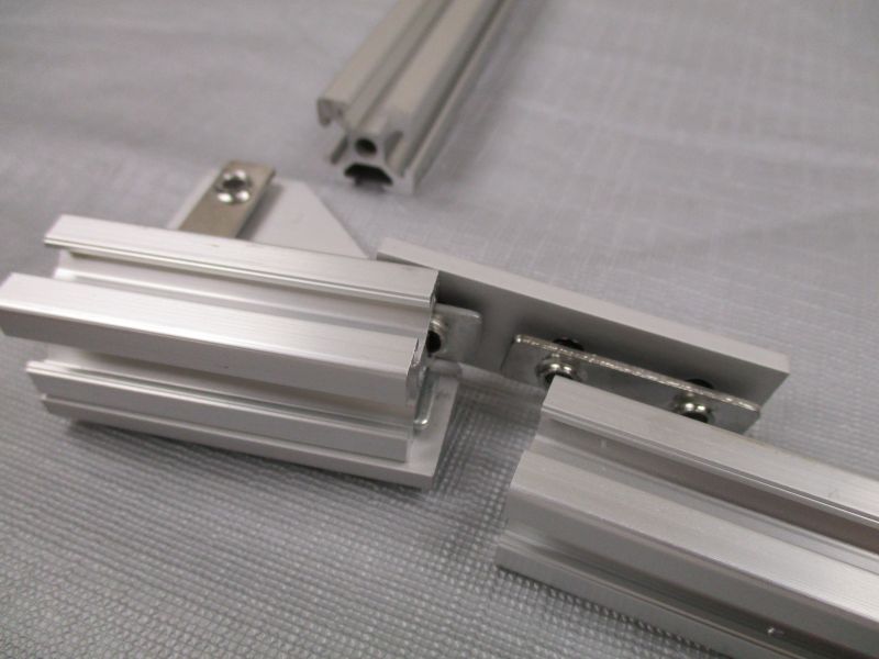
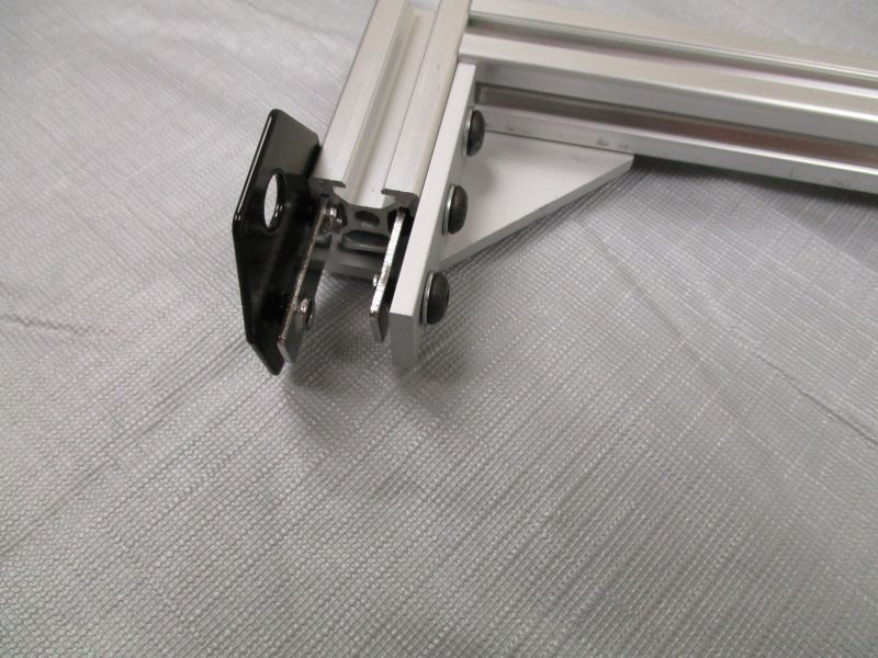
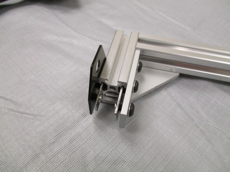
Slide L-Plate onto Handlebar Extender. Use the row of T-Nuts with a Double T-Nut and a Single T-Nut.
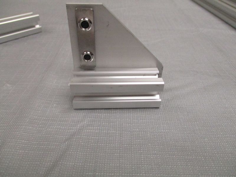
The Handlebar Extender should lie against the corner of the L-Plate.
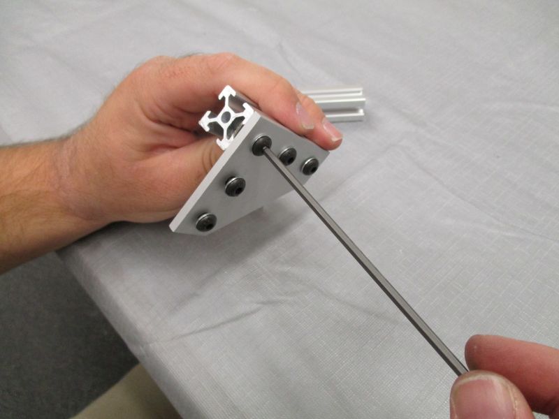
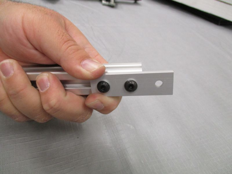
With the Handlebar Extender flush against the corner of the L-Plate, tighten the two screws of the Double T-Nut.

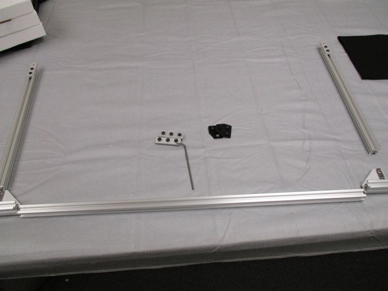
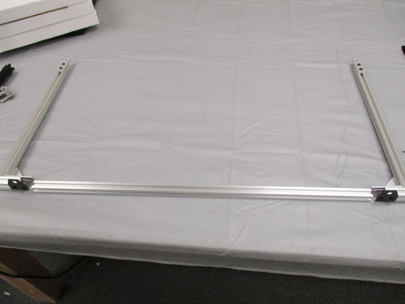
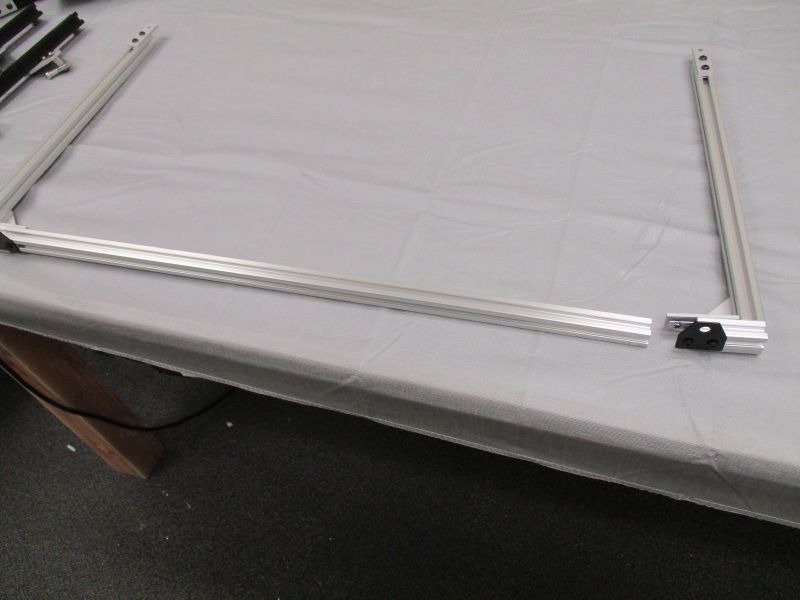
Repeat with second Handlebar Extender and L-Plate. Gather these with Long Beam and (2) Clear Cross Beams and arrange them.
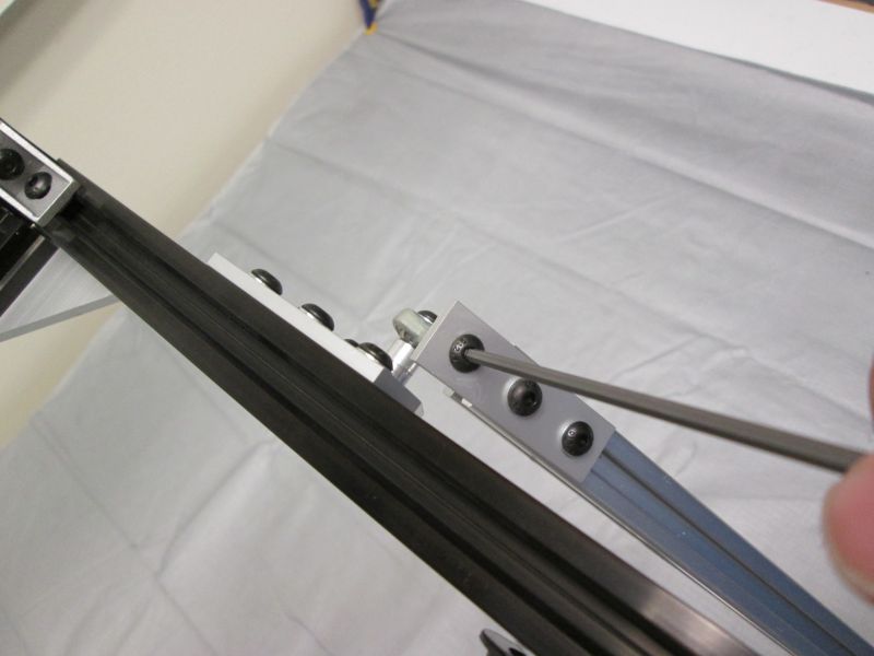
Slide Strip Plate with two screws onto the end of a Clear Cross Beam.
With the Double T-Nut just inside the slot and the Strip Plate parallel to the Clear Cross Beam, snug the screws.
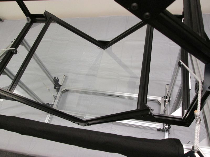
Repeat with other Clear Cross Beam. The ends with the Strip Plates lie on top and face away from the handlebar.
Slide Strip Plate with 3 screws onto Handlebar Extender. The Single T-Nut goes in first.
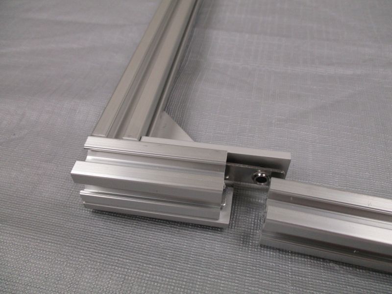
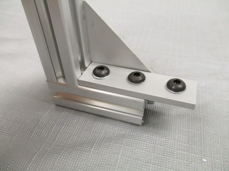
Slide Clear Cross Beam onto L-Plate perpendicular to Handlebar Extender. Tighten 2 screws holding the Clear Cross Beam. The Strip Plate should be flush against the side of the Clear Cross Beam. Snug the screw with the Single T-Nut to hold it in place.
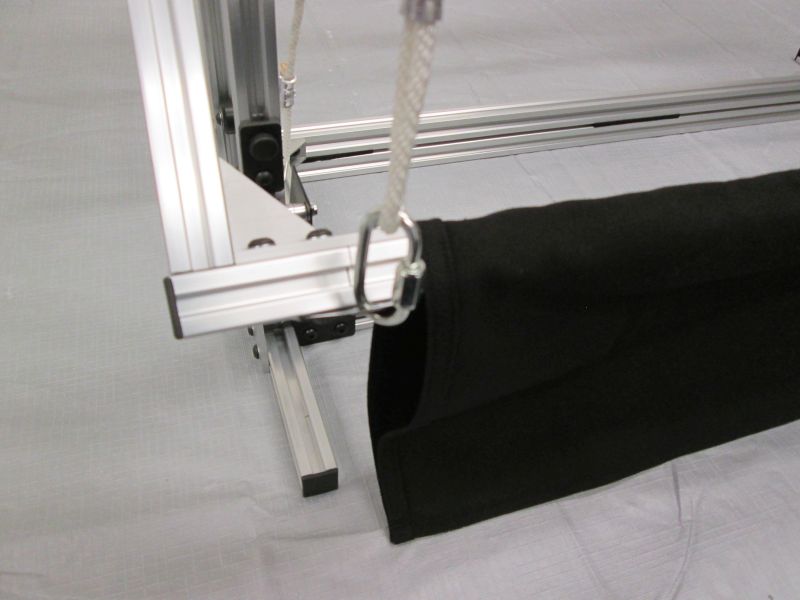
Slide Rope Anchor onto the front of the Handlebar Extender.
The Rope Anchor should be about halfway onto the Handlebar Extender, flush with the bottom. Precise positioning is not important.
Repeat on the other side.
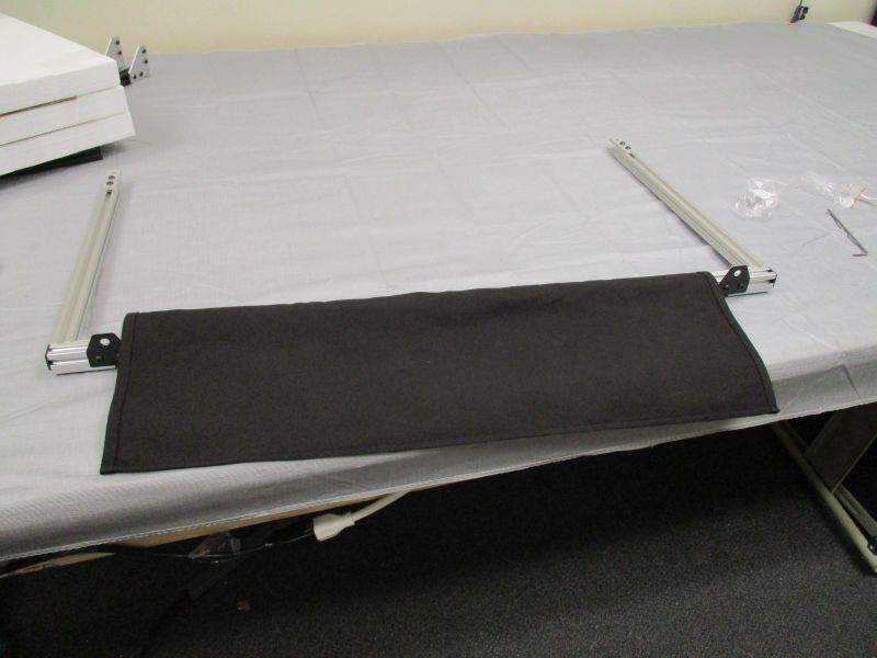
Slide the Long Beam onto one side. With the Long Beam flush and parallel to the Handlebar Extender, tighten the remaining screws. Leave the other side unattached for now.
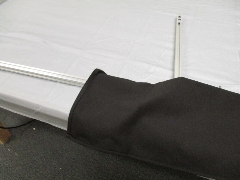
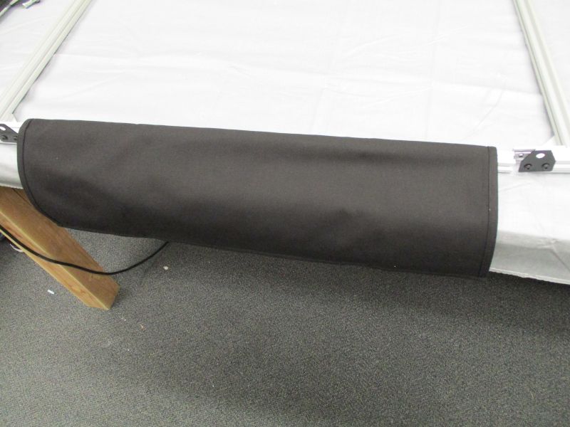
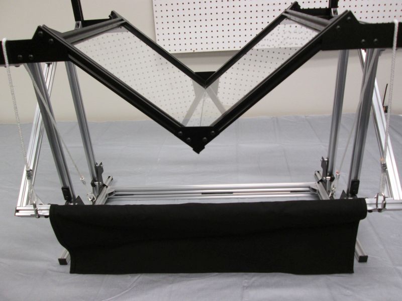
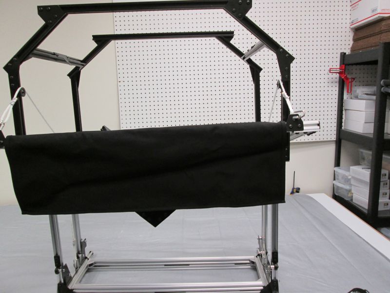
Slide the Counter-weight Bag onto the Long Beam. Attach the Long Beam onto the other side.
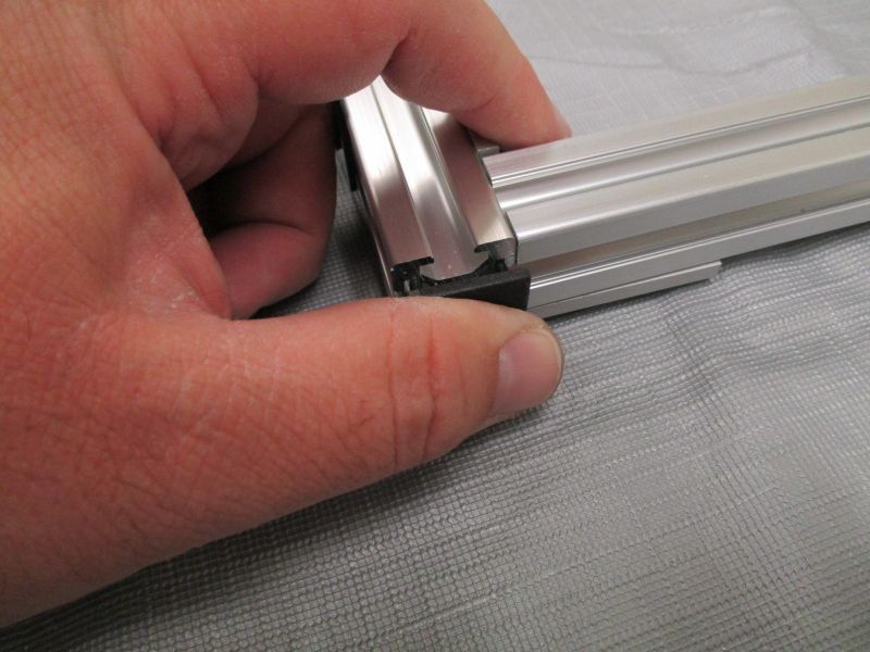
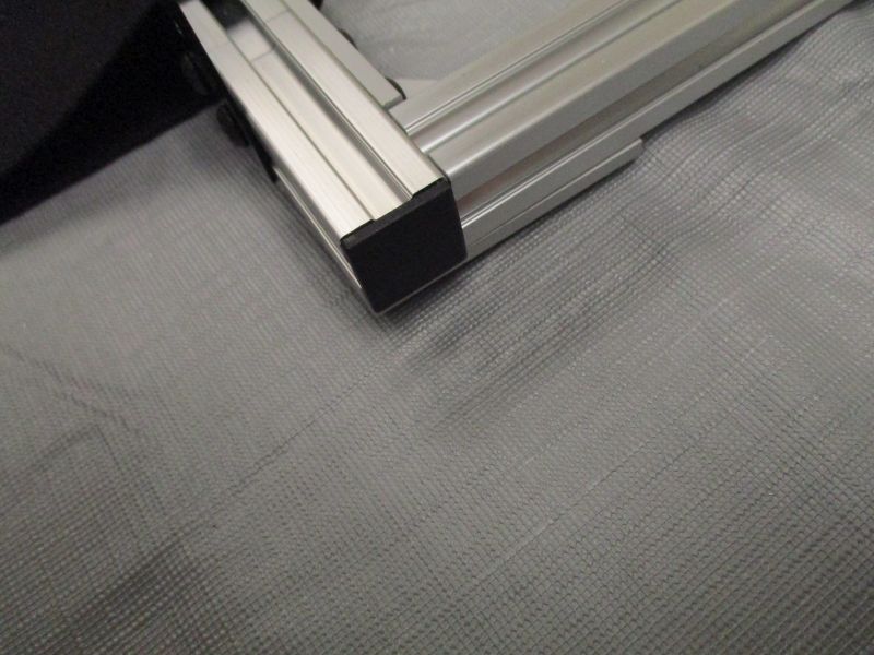
Insert Plastic End Cap into the end of each Handlebar Extender.
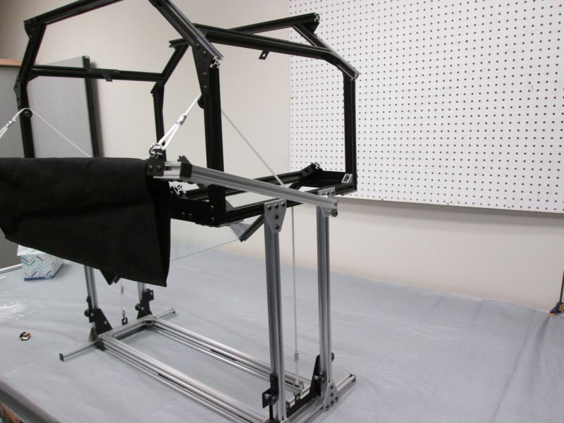
The Handlebar is now complete and ready for attachment.
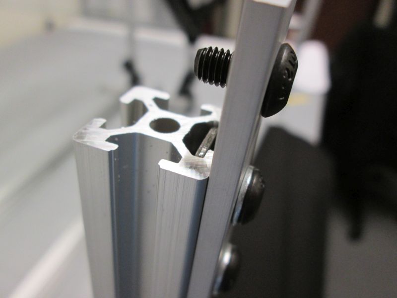
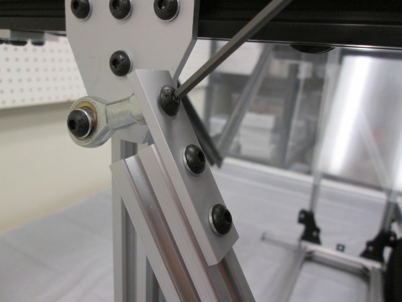
Insert an M5 x 10mm Screw into the third hole of a Strip Plate.
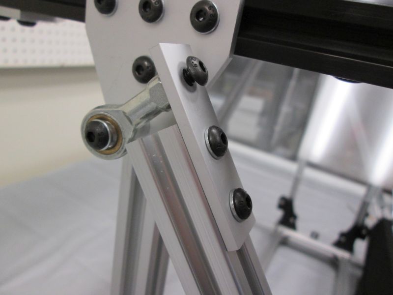
Hold the Handlebar Assembly in place as you screw the M5 x 10mm Screw into the Rod End.
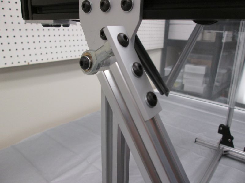
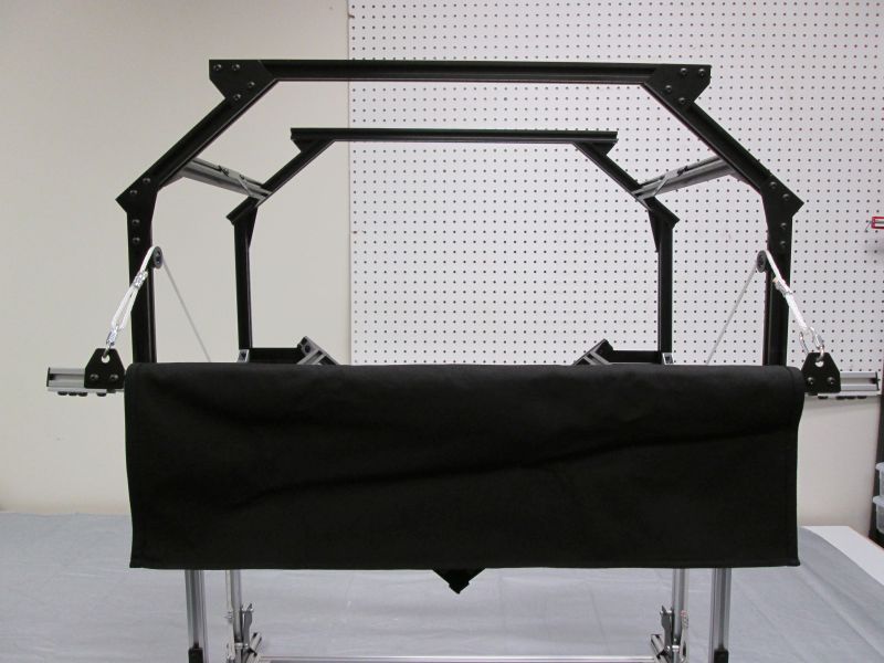
Repeat with other side. The Handlebar is in the front attached to the Rod Ends which are on the rear pair of Vertical Rails.
Snug attachment screws. If Handlebar isn't completely square, loosen screws and adjust as necessary.
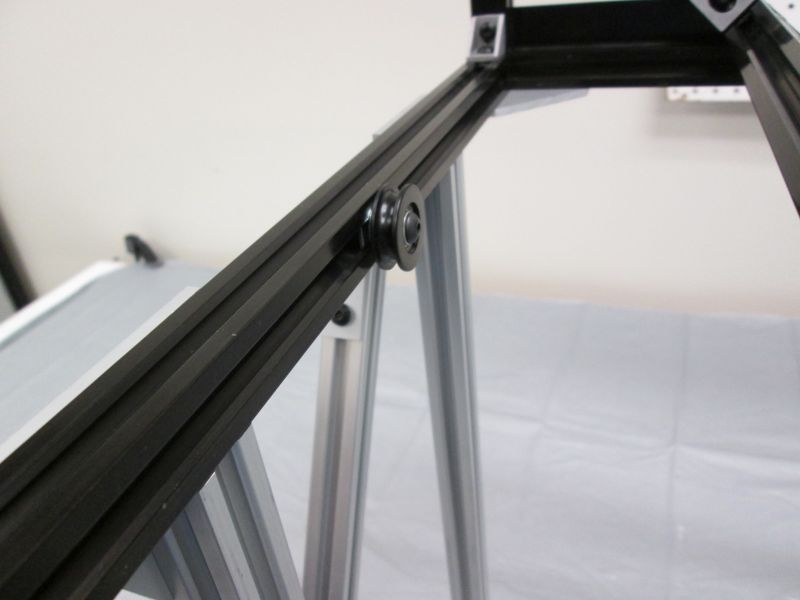
The Pulleys on the side Black Cross Beams should be adjusted so that it is directly above the center of the cradle lifter. Tighten screws.
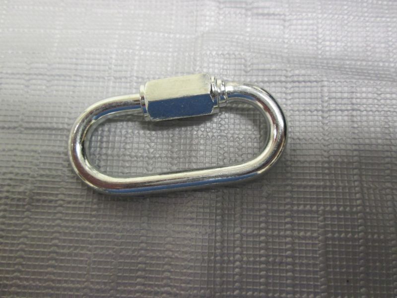
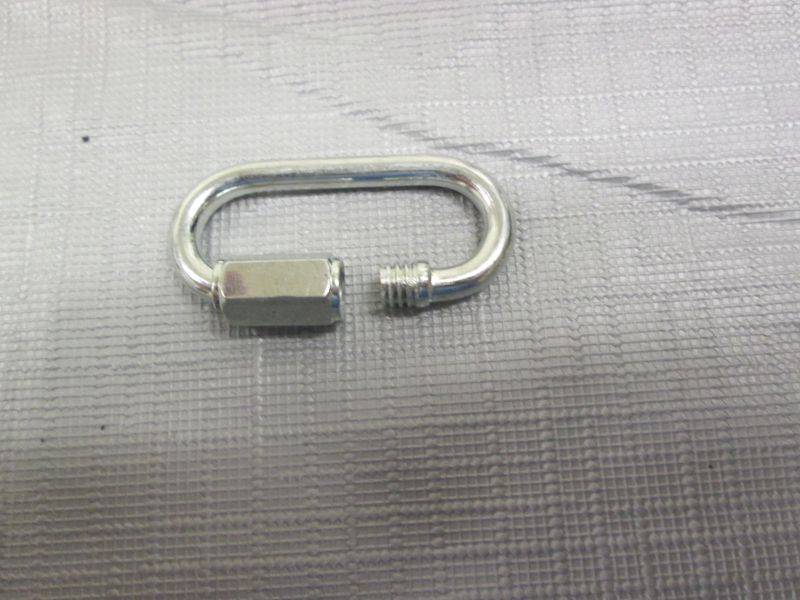
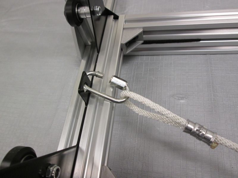
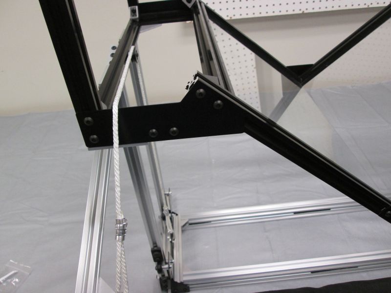
Gather Quick Links and unscrew them.
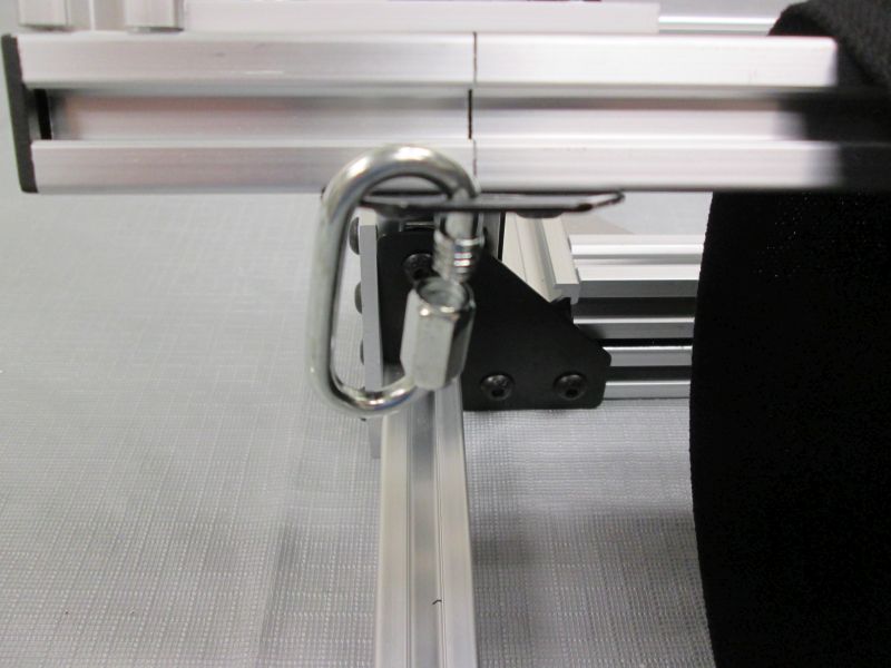
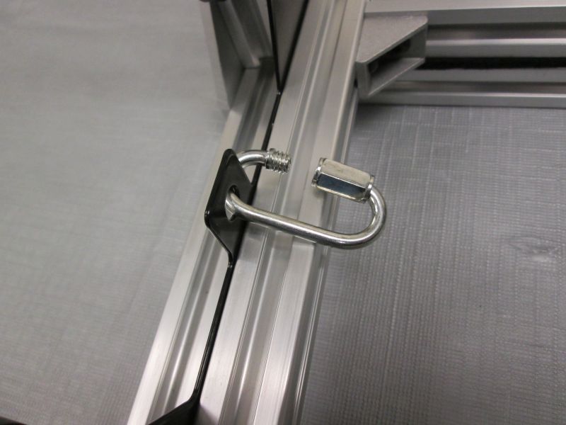
Attach Quick Link to each Rope Anchor.
Attach Quick Link to each Lifter Plate.
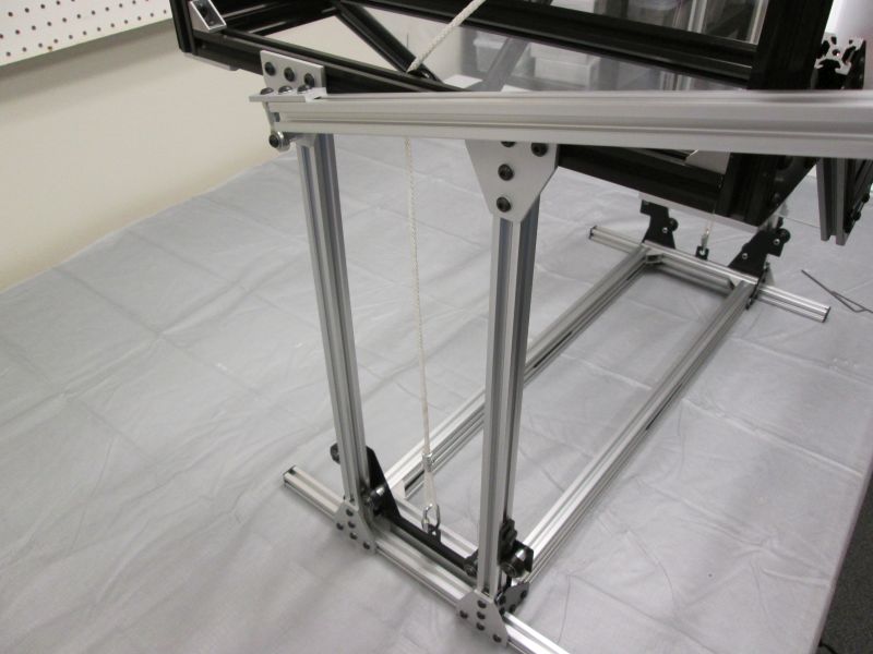
Attach a rope to the Quick Link on the Lifter Plate. Screw the Quick Link to close it.
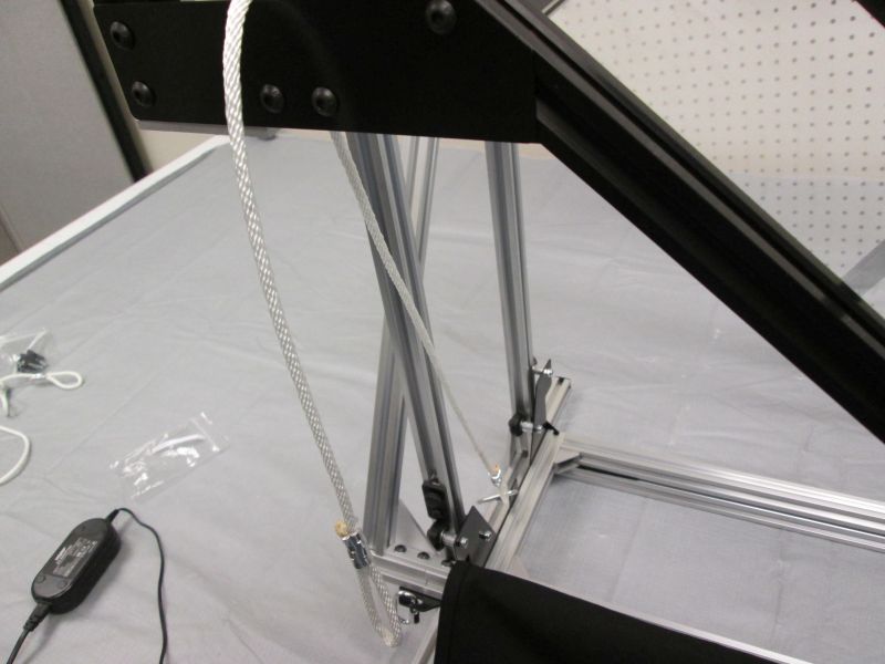
Feed the rope up and over the Side Plate.
Repeat with other side.
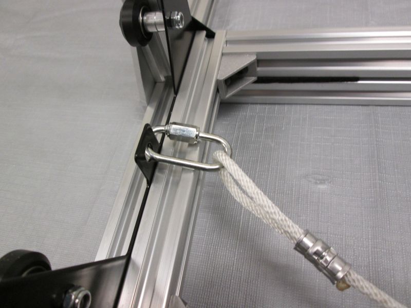
Attach Rope to Quick Link on Rope Anchor. Close Quick Link.
Repeat on other side.
Lift Handlebar. Run both Ropes through the Pulleys on the Black Cross Beams.
Lift Handlebar. Run both Ropes through the Pulleys on the Imaging Columns.
If one rope has more slack than the other, adjust Pulleys on Imaging Columns up and down to take up any extra slack. Tighten screws on Pulleys.
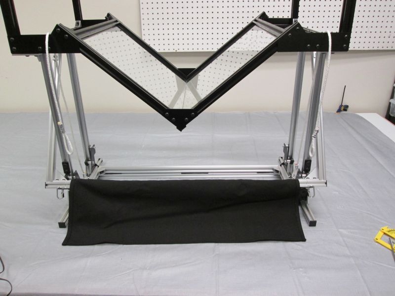
The Handlebar Assembly is complete. Move Cradle Stops up and test handlebar to ensure that the whole mechanism moves smoothly up and down.