Imaging Module
Special Notes
The (2) Camera Bolts and (6) 1/4" Washers are used for mounting your cameras after assembly is complete.
Inventory
Tools needed:
- 3mm Hex Key (in Tool Bag)
Parts needed:
- (1) Imaging Module Bag
- (2) Black Cross Beam
- (4) Imaging Column
- (4) Imaging Strut
- (2) Imaging Beam
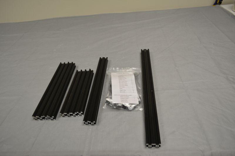
Gather parts together and remove plastic coating from extrusion pieces if necessary. Use the part list in the Imaging Module Bag to verify that all parts are present before beginning. Notify help@tenrec.builders if any parts are missing.
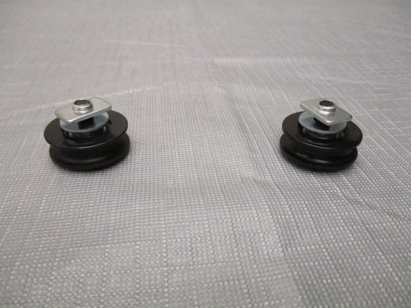
Preload (2) Pulleys
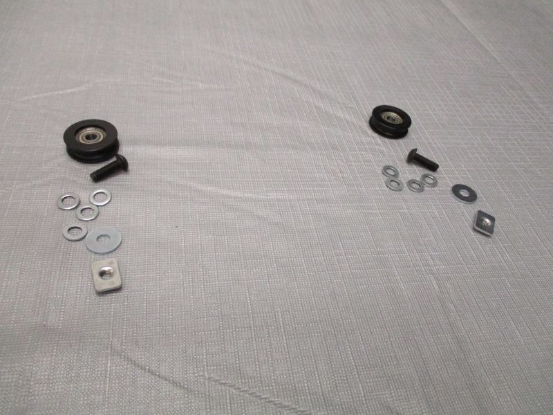
Each Pulley uses (1) M5 x 16mm Screw, (4) M5 Washers, (1) M5 Fender Washer, and (1) Single T-Nut.
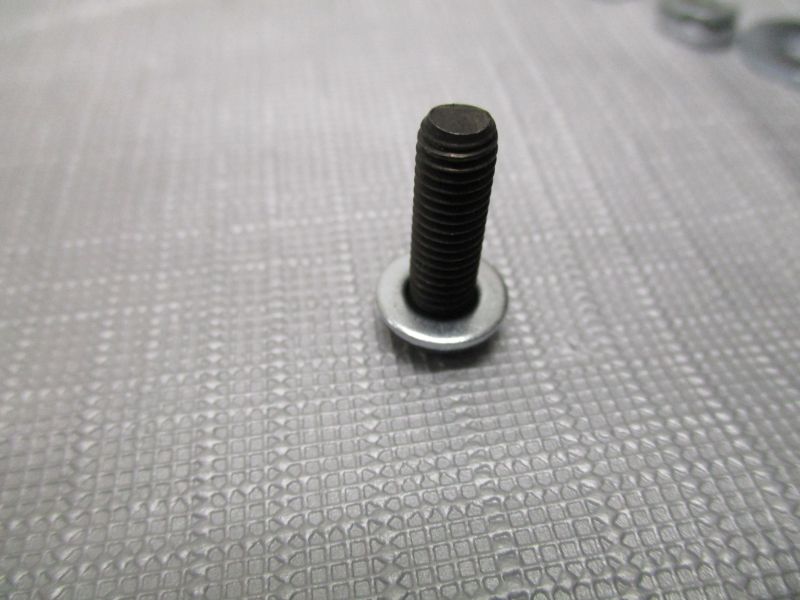
Place M5 Washer on M5 x 16mm Screw.
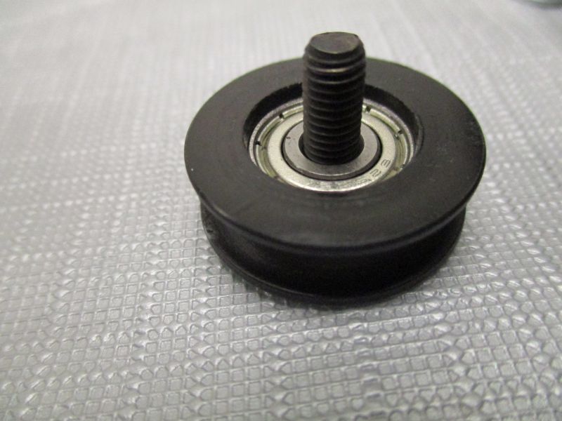
Place Pulley on M5 x 16mm Screw.
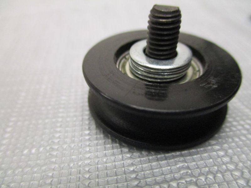
Place (3) M5 Washers on M5 x 16mm Screw.
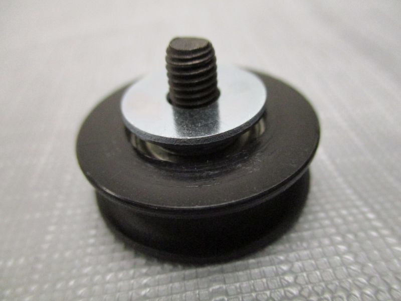
Place M5 Fender Washer on M5 x 16mm Screw.
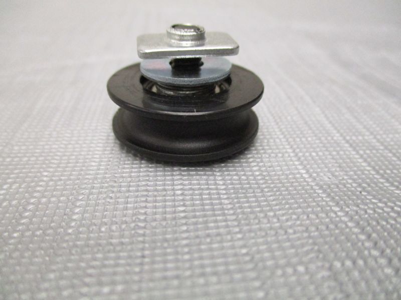
Screw Single T-Nut on M5 x 16mm Screw. Leave a gap to allow sliding onto T-Slot extrusion.
Preload (2) Camera Plates
Each Camera Plate uses (2) M5 x 6mm Screws and (2) Single T-Nuts.
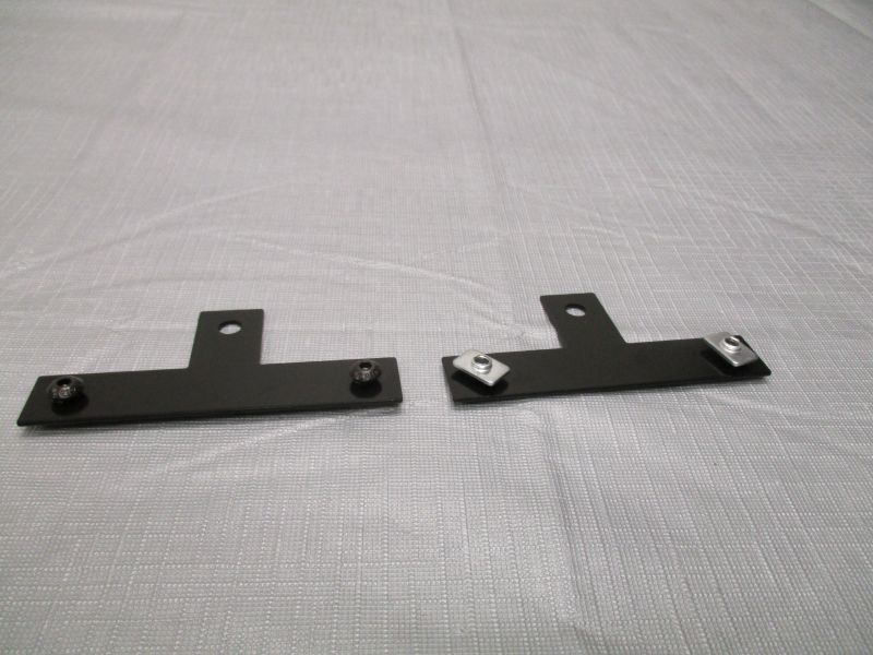
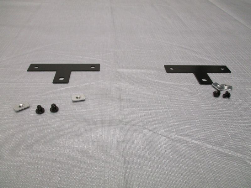
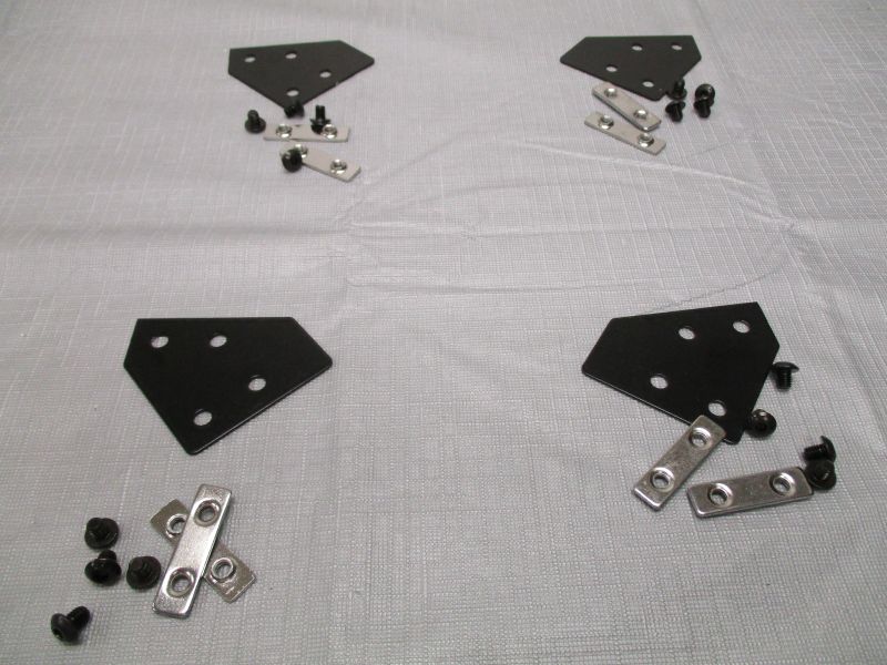
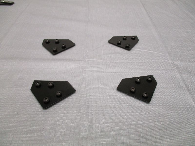
Preload (4) Imaging Brackets
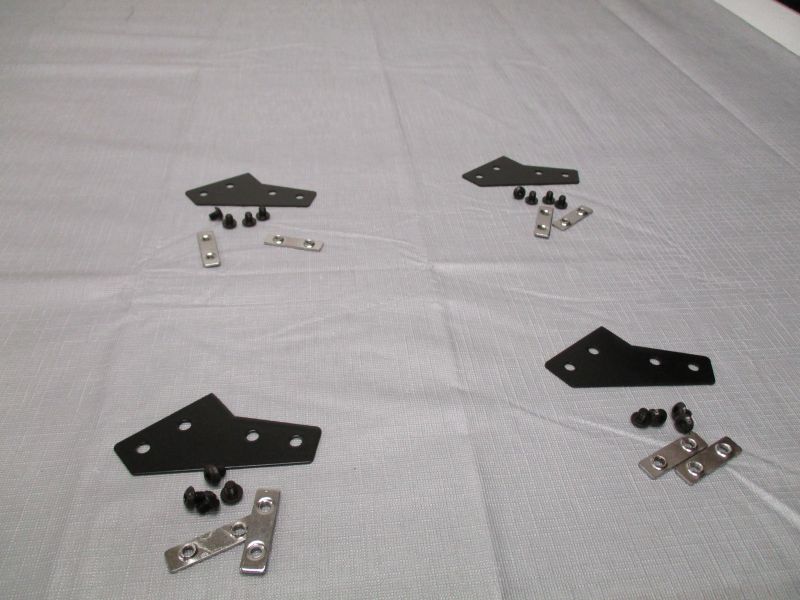
Each Imaging Bracket uses (4) M5 x 6mm Screws and (2) Double T-Nuts.
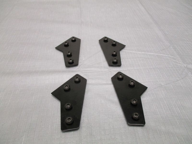
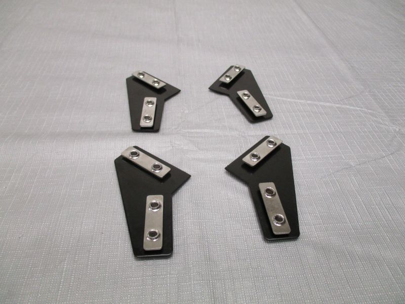
The Imaging Brackets should be in two left/right pairs which are mirrors of each other.
Preload (4) Imaging Top Plates
Each Imaging Top Plate uses (4) M5 x 6mm Screws and (2) Double T-Nuts.
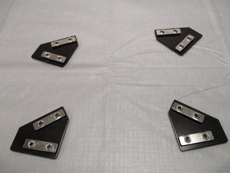
The Imaging Top Plates should be in two left/right pairs which are mirrors of each other.
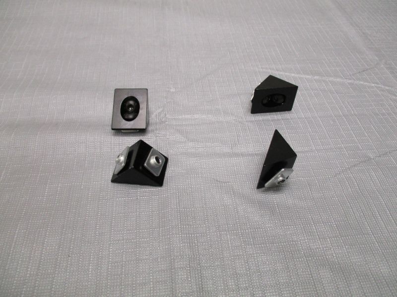
Preload (4) Black Corner Brackets
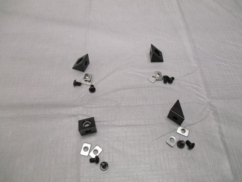
Each Black Corner Bracket uses (4) M5 x 8mm Screws and (4) Single T-Nuts.
Assemble Imaging Beams
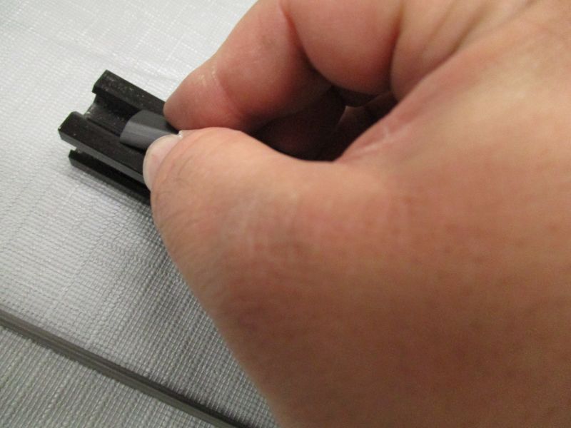
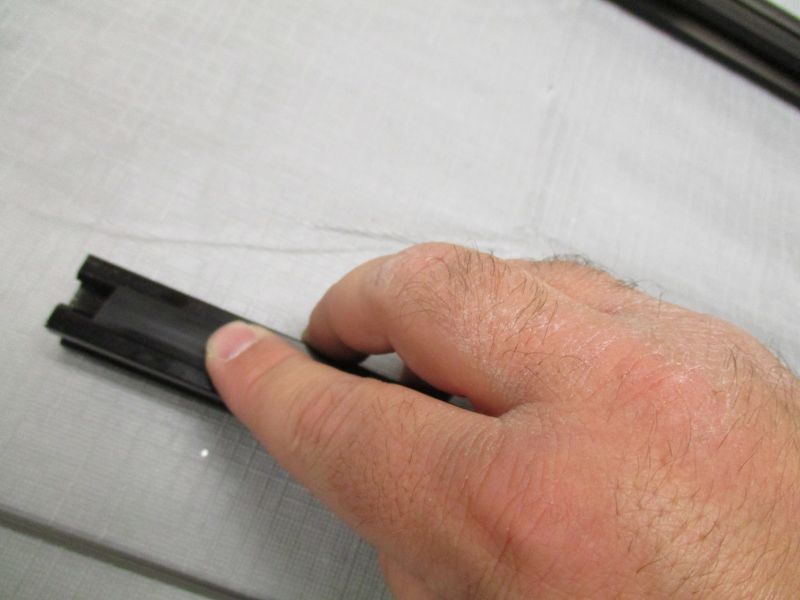
Insert Slot Cover near the end of an Imaging Beam. Pinch Slot Cover and then push into slot. Press down along the length of the Slot Cover.

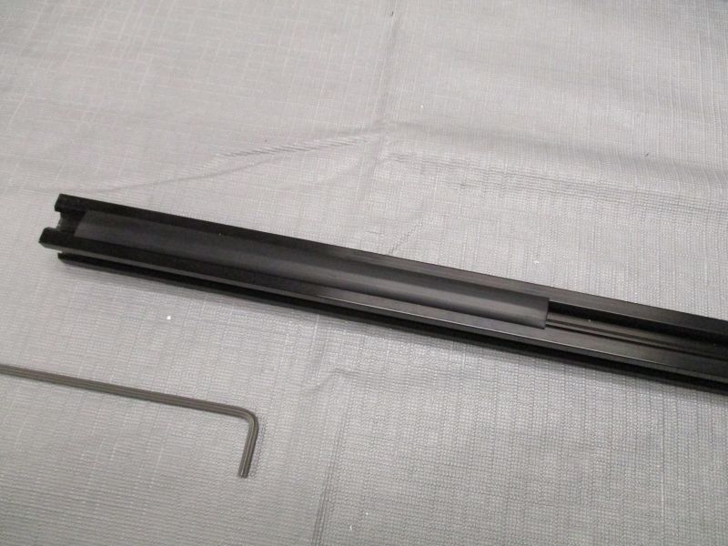
Repeat at other end of Imaging Beam. Repeat for other Imaging Beam. The side with the slot cover will be the top of the Imaging Beam.
Assemble Black Cross Beams
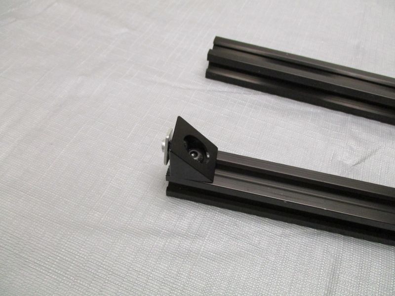
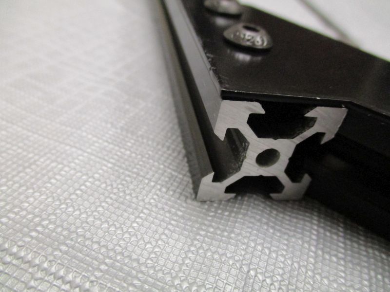
Slide Black Corner Bracket into end of Black Cross Beam. Snug screw.
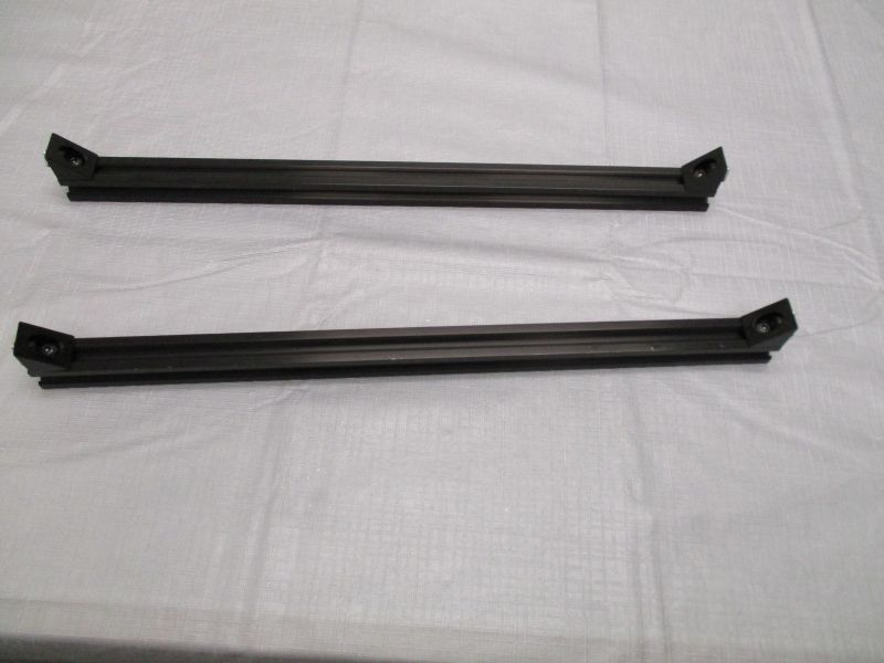
Repeat with other end of Black Cross Beam. Repeat with other Black Cross Beam.
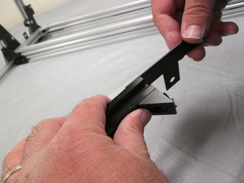
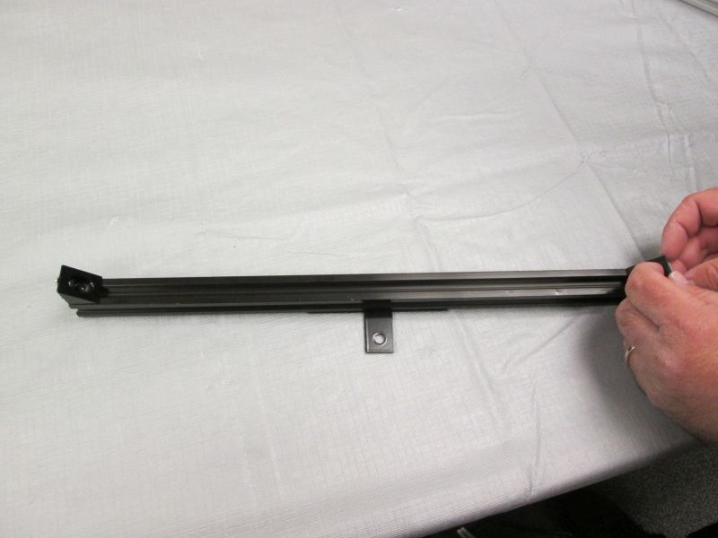
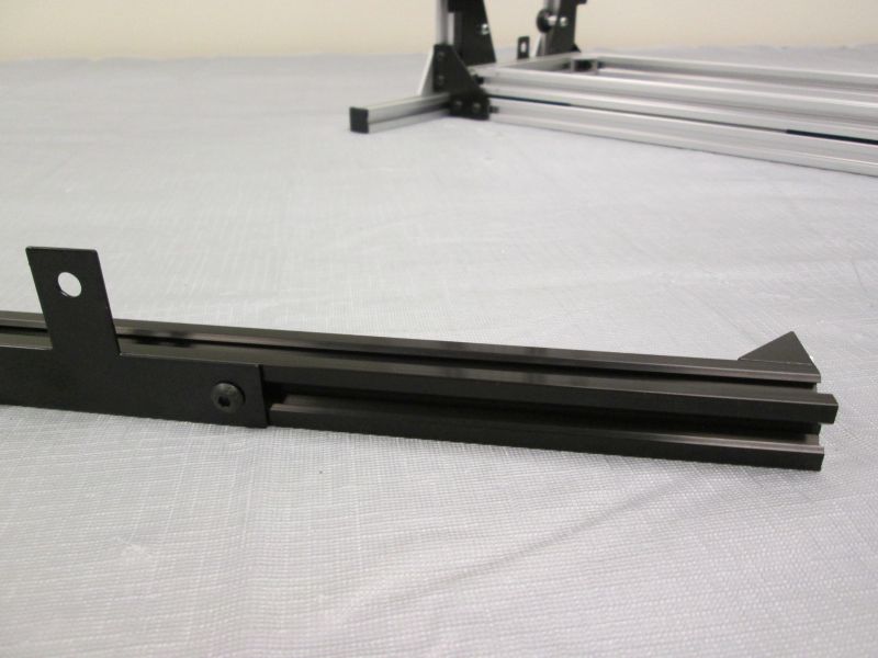
Slide a Camera Plate onto each Black Cross Beam on the opposite side of the Black Corner Brackets. Snug screws.
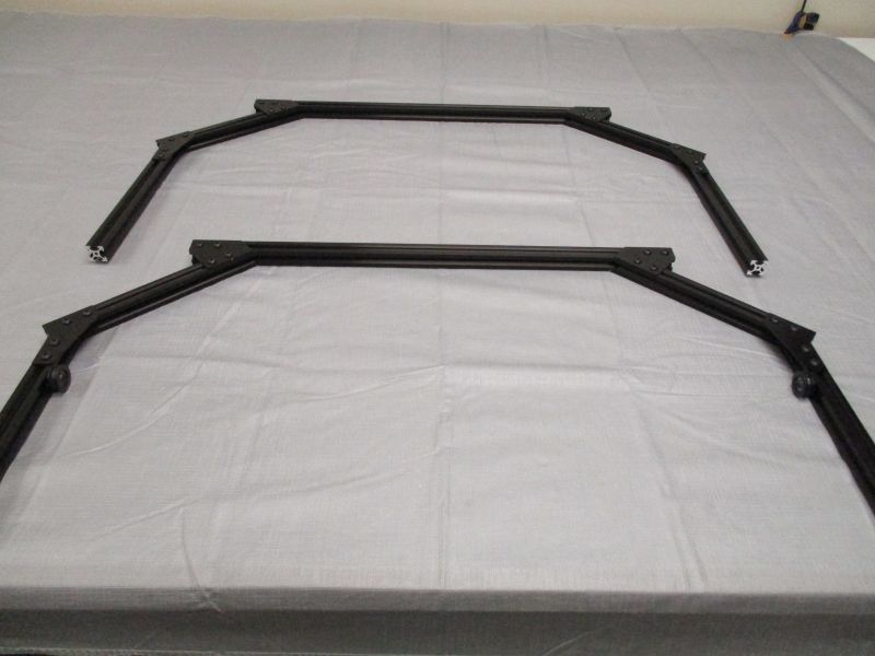
Assemble Imaging front and back
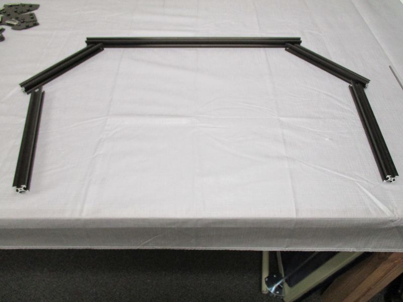
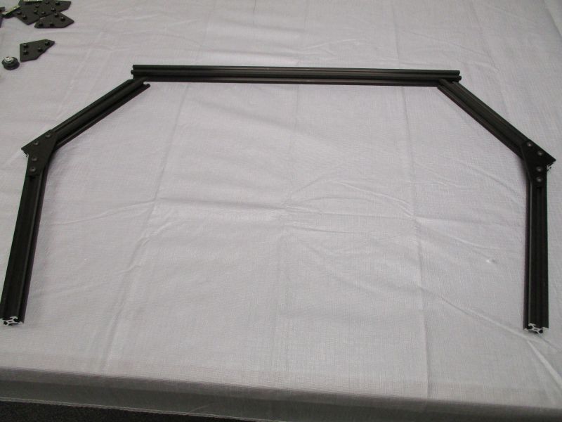
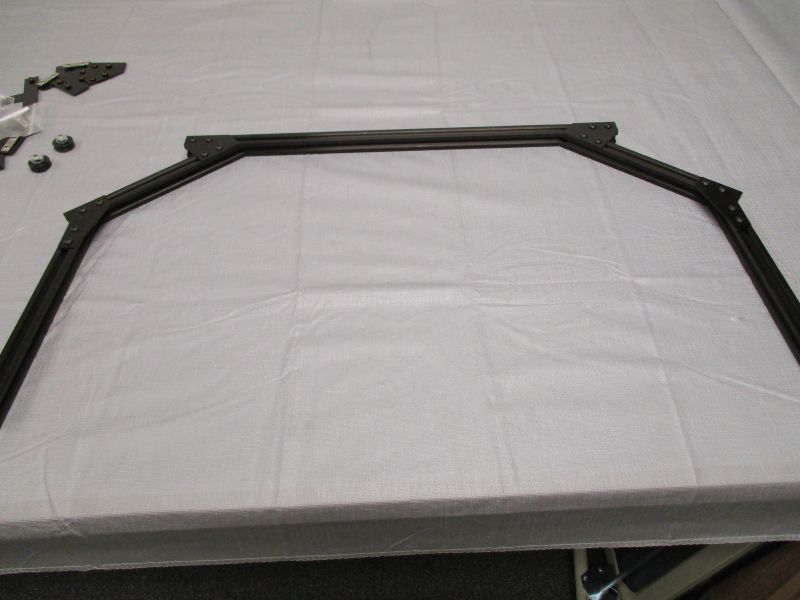
Arrange (2) Imaging Columns, (2) Imaging Struts, and (1) Imaging Cross Beam as shown. The top of the Imaging Cross Beam with the slot cover faces away from the Imaging Struts.
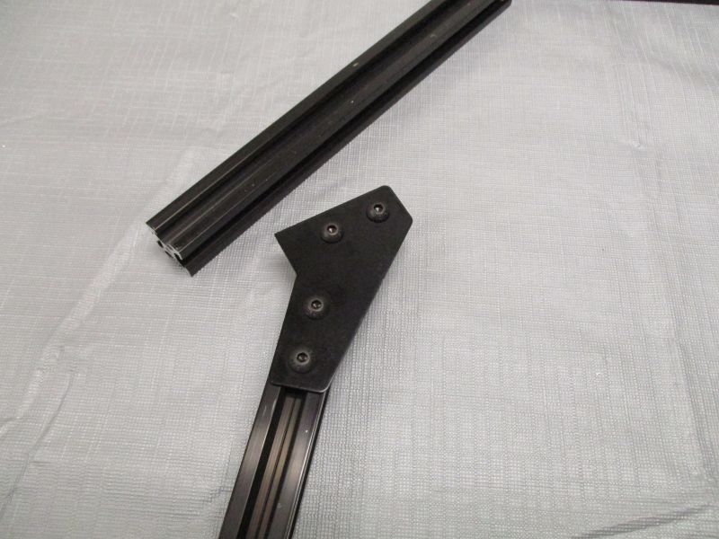
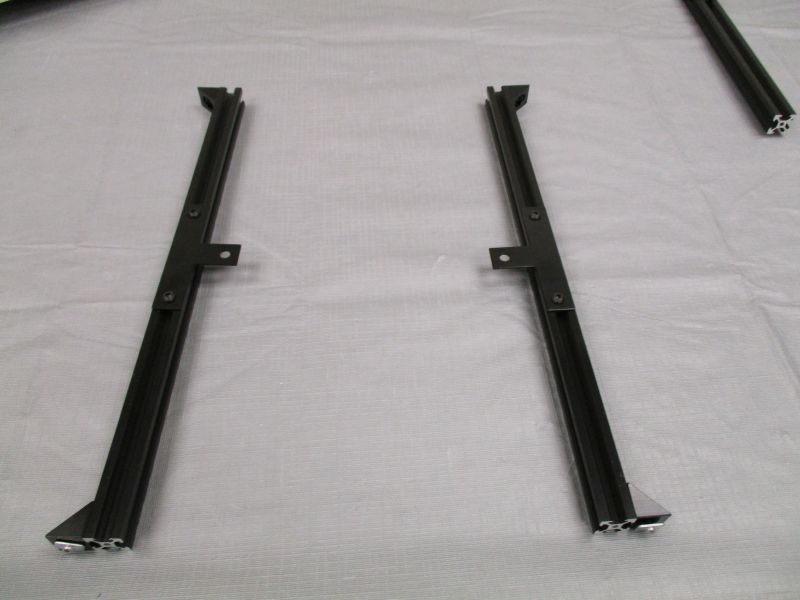
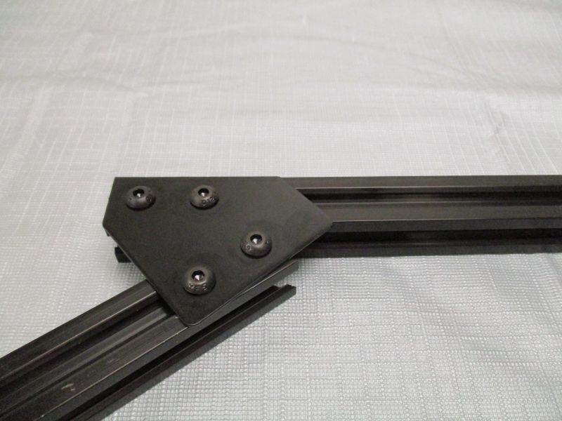
Slide Imaging Bracket onto Imaging Column.
Slide Imaging Bracket onto Imaging Strut.
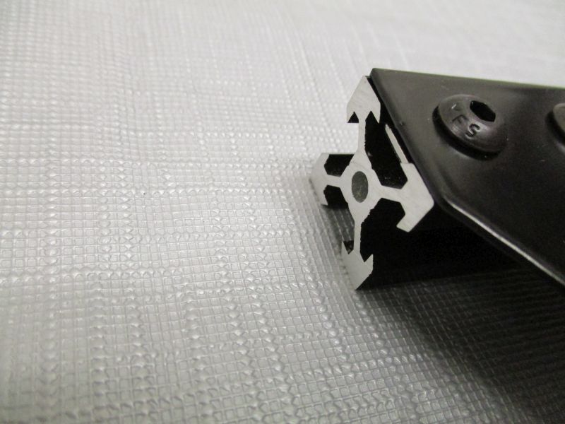
The end of the Imaging Strut should be flush against the corner of the Imaging Bracket. The Imaging Column should rest against the Imaging Strut with one side flush against the Imaging Bracket. Tighten screws.
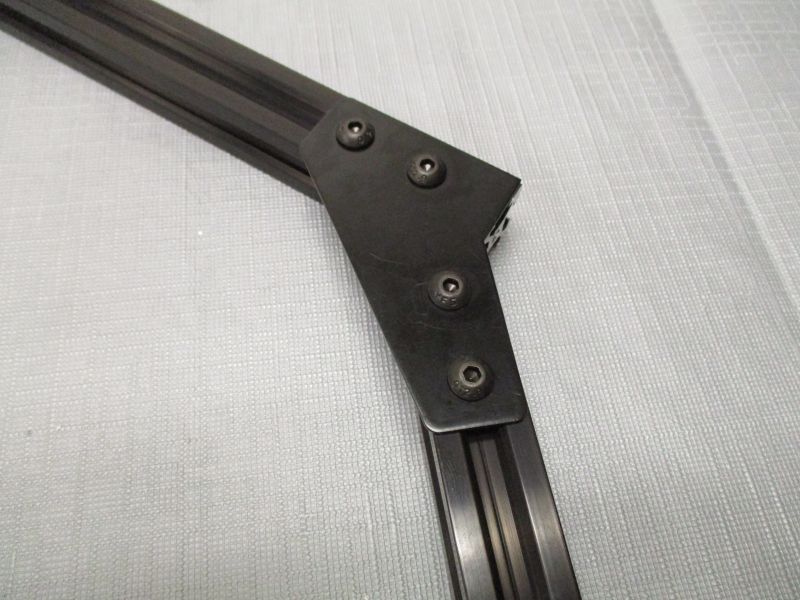
Repeat on the other side.
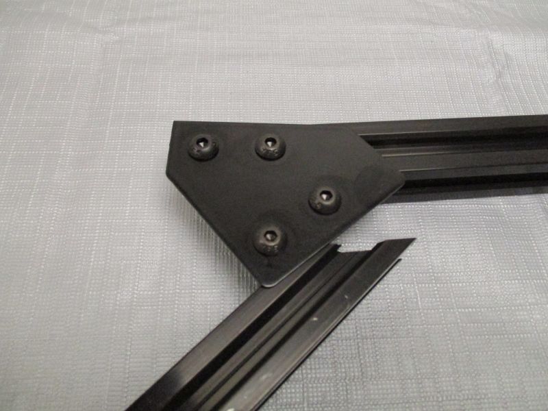
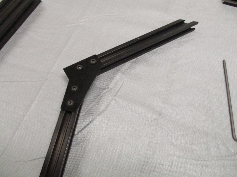
Slide Imaging Top Bracket onto Imaging Beam.
The corner of the Imaging Top Bracket should be flush with the end of the Imaging Beam.
Slide Imaging Strut onto Imaging Top Plate. The end of the Imaging Strut should rest against the bottom of the Imaging Beam and lie flush against the side of the Imaging Top Plate. Tighten screws.
Repeat on the other side.
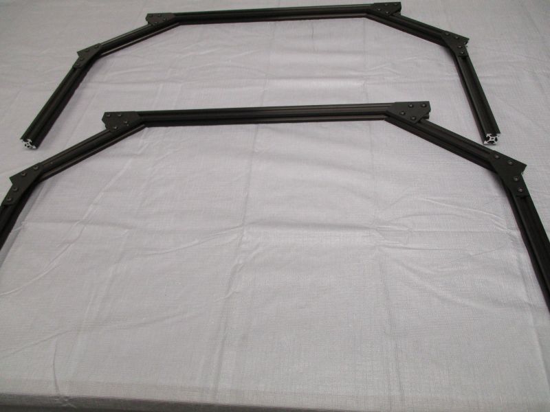
Repeat these steps. You will now have two identical assemblies. One will be the front and one will be the back of the Imaging module.
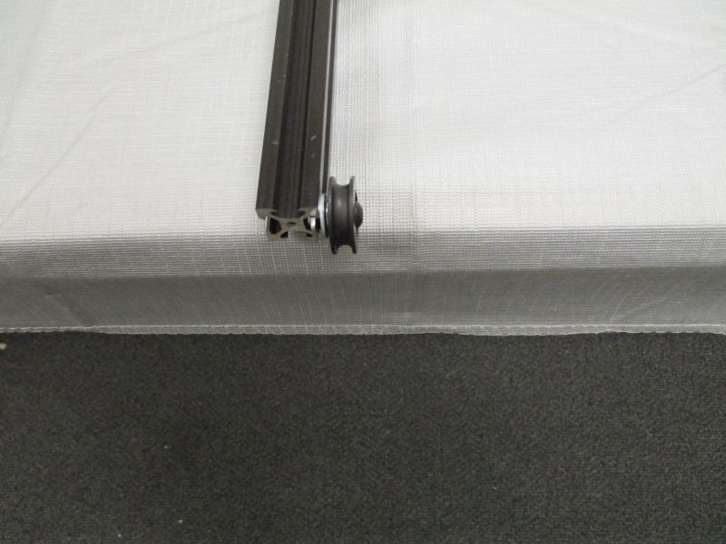
Pick one of the assemblies to be the front. Slide a pulley onto an Imaging Column of the front assembly.
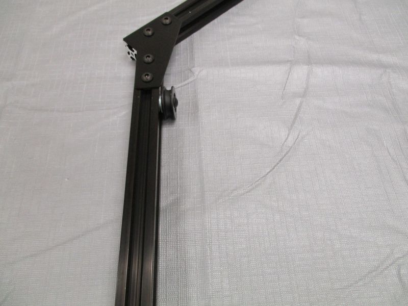
Slide pulley up until it is near the bottom of the Imaging Plate. Snug screw.
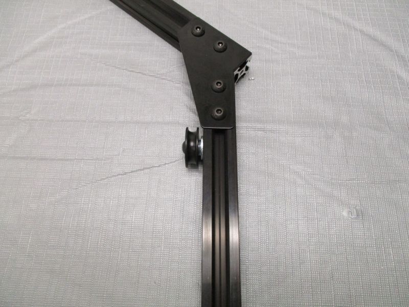
Repeat on the other side.
The Imaging front and back are now complete.